Hygienic (sanitary) design when using solids
|
Here you will find answers to the following questions:
|
1 Introduction
Hygienic (sanitary) design means easy-to-clean, self-contained facilities with little dead space.
In the event of improper and open handling, solids, unlike liquids, can be distributed throughout the entire building through the ventilation system or by being carried over on surfaces or by personnel. Subsequent removal of contamination from all surfaces in order to avoid cross contamination can be very expensive and time-consuming or even impossible, depending on the room and facility planning. Therefore, the facility design to be used is of the utmost importance and should be taken into consideration during the early stages of planning.
The internal parts must be dead-volume-free (dead legs) and easy to clean. There should preferably be no attachments on the equipment components, as these only reduce the ease of cleaning. But in the solids area in particular, this is difficult to implement. For example, when filling an API after drying, it may be necessary to crush agglomerates, which requires the installation of a crusher with a screen.
Representative samples of the products are drawn with a sampler. The product is then filled into a temporary container or sales container via a metering system, at times with an extremely high degree of accuracy. This all means a significant number of mechanical facility components are required, which also have many attachments in the product flow.
Cleaning here is not always possible with CIP (chapter 4.I CIP (Cleaning in Place)). WIP (Washing in Place) is more realistic with subsequent dismantling of the critical facility components for manual cleaning. These critical parameters must be taken into consideration before and during cleaning validation and documented in the SOP. If the facilities and equipment are to be opened in the meantime, hygienic design also plays a key role in the external area. In particular in clean rooms, where special requirements are made in terms of cleaning the facilities and surfaces, there must be as few attachments, cable ducts, etc. as possible. But also outside clean rooms, the facility design is important for emptying or filling, as this is in the immediate vicinity of the product and an increased level of cross contamination can occur here. In addition, it must be considered whether or not the facility is a mono-purpose or multipurpose facility and, for clean rooms, the clean room category is important e.g. A, B, C and D. Each area requires its own facility design, which must be defined and documented in the user requirements during the early planning stages.
Examples:
- External surfaces ground to a required surface finish
- No open cable ducts
- Cladding of attachments such as drives should be routed from the clean room area to the services area. (This also makes maintenance and repair of the facility easier).
1.1 Weaknesses in facility planning
During facility planning, the area of solids supply and removal is often only taken into consideration after the room or building planning has been completed. Often rooms or buildings are already under construction before the supply and filling of solids is considered. Take, for example, the field of API Production: the reactors and crystallisers are usually accommodated in the upper stories, the centrifuges in the middle stories and the dryers in the lower stories. Equipment inlet and outlet heights for the solids feed must be taken into consideration, as the raw materials are sometimes delivered in large containers. This is similar for facility planning in drug product production, except that the solid already plays a key role here and is usually taken into account from the outset.
In cases in which the solids feed is not taken into consideration, the solids can no longer be supplied or emptied by gravity. They must be supplied to the facilities through transport systems (e.g. power transport system - PTS, see chapter 4.J.11 Containment on equipment), in order to feed the solid to the reactors or to load a tablet press, for example. When emptying dryers, centrifuges in API production and blenders in formulation, a pneumatic converging system must be used if the room is not high enough.
Another weakness is the facility design. Most APIs are filled in a classified room after drying, but the room design is often inadequate. The wall design and room planning with GMP conform passages often have weak points. The solids facility design too is often given too little attention during planning. Open pipes, open cable ducts and unfavourable facility design of the surfaces are not rare occurrences, and cleaning of the solids facility is often impossible.
2 Surfaces
2.1 Product-contact surfaces
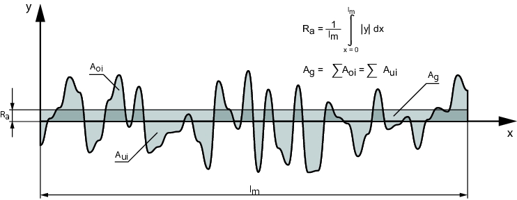
The definition of the required surface finish plays a key role in the quality and hygienic design of a solids system. A high quality surface on the product-contact and non-product-contact parts significantly diminishes the sediment of products (solids) and also the growth of micro-organisms. A guide value of Ra Ј 0.8 mm has prevailed for product-contact surfaces (figure 1).
 |
But values of less than 0.8 mm are not rare. On the contrary, the frequency of installations for which a value of Ј0.5 mm is required is constantly increasing. The reason for this is certainly that the size of bacteria has become a basic criteria for this assessment. The size of bacteria is between Ј0.5 and 5 mm. Yeast and fungus are bigger than bacteria. Only viruses have sizes in the nanometer range. It is only possible to manufacture surfaces in the nm range by using very expensive technologies and this has not been economically possible to date. In addition, the growth of viruses in a facility is improbable as only a small minority of viruses can multiply or survive outside a host.
A surface finish of Ra 0.8 mm can be manufactured up to a thickness of 6 mm by using cold rolled sheets (IIIC see figure 2), without having to post-process the surface with grinding or polishing. Mechanical post-processing would only deteriorate the surface finish of a cold rolled sheet.
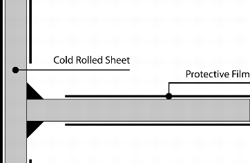 |
Figure 2 Protective film on cold rolled sheets should only be removed where necessary for processing. |
During processing (such as welding) of cold rolled sheets, it is important, during the production steps, to leave the sheets in the double-sided protective films applied after they leave the roller. The protective films should only be removed in the areas in which mechanical processing takes place or where a welded seam has to be produced. To polish the processed surfaces, the film ends are reinforced with an adhesive tape. This prevents the sheet underneath the film from being polished too (figure 2).
For hot rolled sheets or welding seams, a surface finish of Ra Ј 0.8 mm can only be achieved through mechanical polishing with grinders. During final grinding of the area to be processed with a grain size of 240, the required surface finish of Ra Ј 0.8 mm is achieved.
Another type of surface finishing is electropolishing (electrolytical polishing, anod. polishing). Electropolishing is the smoothing of metallic surfaces through galvanic abrasion of the peak-to-valley height in an electrolyte. Electropolishing has the effect of improving the surface finish through the abrasion of surface peaks and lends the metal a glossy appearance. The procedures for electrochemical polishing and deburring are, in principle, a reversal of the galvanic process. Under the effect of direct current, metal is removed from the anodic wired workpiece surface into a special electrolyte. The abrasion is carried out with no load and preferably extends to the micro-roughnesses. The surface is smooth and glossy in the micro-range. This is therefore called "electropolishing". Structures in the macro-range are retained, but their surface is smoothed and rounded, depending on their shape. Edges and corners face tougher abrasion, which causes a reliable fine deburring of the entire surface area (electrochemical deburring).
Yet the use of this procedure has dropped sharply in the pharmaceutical and API production industry in recent years, and there are only a few applications remaining which use this additional type of surface treatment. The reason: Some products tend to adhere to electrolytically produced surfaces. This means that the simple emptying and easy cleaning remains elusive in very expensively processed parts. Another disadvantage: Not all materials can be electropolished (see chapter 3 Material: stainless steel and figure 3 to figure 9). The surface finish is measured and documented by a stylus instrument.
 |
 |
|
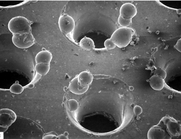
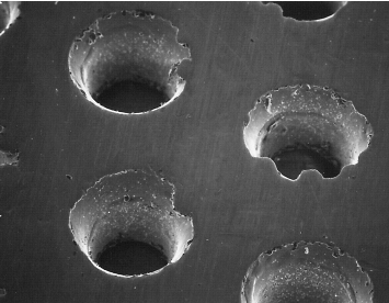
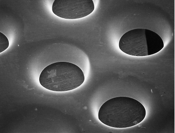
Figure 3 Surface of a filter sheet - starting status |
Figure 4 Ground to achieve rough deburring |
 |
 |
|
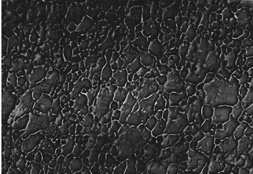
Figure 5 10 min electropolished |
Figure 6 CrNi-steel surface (1000 times enlarged) blasted with aluminium oxide |
 |
 |
|
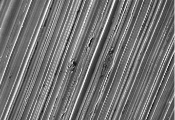
Figure 7 Ground grain size 180 |
Figure 8 Surfaces (IIIc) |
 |
Figure 9 Electropolished |
2.2 Non-product-contact surfaces
The external surfaces of facilities and equipment (the surface facing away from the solid) are dealt with in a slightly different manner than the internal surfaces. If the solids facility uses a closed process, no particular significance is generally placed on the external surface. If the room in which the facility has been set up still has platforms and steal beams made from coated carbon steel, the non-product-contact stainless steel parts remain mechanically untreated with a roughness of Ra > 3.2 mm. In this environment, coated carbon steel parts can be used, provided they are not welded to parts that are in contact with the product. Welding carbon steel parts and stainless steel parts directly together should be avoided, as this causes the stainless steel to mingle with the carbon steel. This can lead to rust within the product-contact area.
If the facilities and equipment are set up in a controlled area (e.g. clean room), the following implementation options are available:
- Untreated external surfaces Ra > 3.2 mm, untreated, pickled and passivated welds (see Welds and figure 11):
This variant is very rarely used in controlled areas. The surface finish of Ra > 3.2 mm should only be used if the filling or emptying process is completely closed and no external contamination can take place. This external surface treatment can also be used if the product is an intermediate stage and the same product is always produced on the facility (mono production). - Exterior surface with grinding pattern grain 180, pickled and passivated welds:
This variant is frequently used in API production and also partly in drug production. The grinding pattern on the external parts means the facility already achieves a fine surface. The unprocessed welds are adapted to the grinding pattern with a brush. - External surface with grinding pattern 180, welds subsequently levelled or ground around the radius, if they are fillet welds (parts welded in the corner joints). This implementation is a very elaborate facility finish in the external area, which also enables simple surface cleaning.
- The highest quality variant is grinding (polishing) of the external surfaces to a specific surface finish. This concerns surfaces and welds. Usually, the surface quality is slightly lower for welding seams. In general, on such a high quality facility, the surfaces are ground to a surface finish of Ra < 1.2 mm and the welds to a surface finish of Ra < 1.6 mm. This surface finish is usually implemented in controlled areas of multipurpose facilities, in order to be able to clean the facilities more easily, even in the external area. If highly toxic or highly hazardous APIs and carcinogenic, mutagenic or reproduction-toxic APIs or medicinal products (CMR substances) are produced in a facility, the external surfaces, including welds, are produced up to Ra < 0.8 mm, in order to be able to clean them more efficiently in the event of contamination with the API.
3 Material: stainless steel
While stainless steel has been used for many years already as a material for product-contact and non-product-contact surfaces in the pharmaceuticals industry, this trend has only recently been recognised in API production.
One exception is the last synthesis step for the production of the pure API. Here, the facility technology has been produced completely in stainless steel even in the filling area. The stainless steel material used is available in various compositions and qualities.
The different material qualities start with lowest quality stainless steel (1.4301) and extend to titanium, a material that is extremely expensive and also very difficult to process. For this reason, we will consider materials up to Hastelloy here. This material is also expensive, but is now used in the solids area where aggressive solvents are used.
Figure 10 gives an overview of the most frequently used stainless steels.
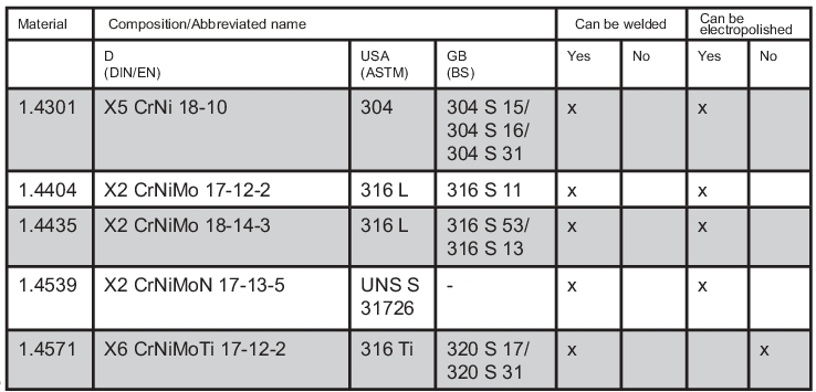 |
When processing the selected material, please note the following:
- Absolute black-white separation in the processing and storage of materials (stainless steels). This means that only materials made of stainless steel are processed in the stainless steel processing area. Normal steel parts may only be found in this area if they are not mechanically processed there. This area must not contain any normal steel parts that have rust on their surface. The risk that the rust will be transferred from the normal steel parts to the stainless steel parts is too high. On the rolls, for example, (for sheet processing) no material mixture of normal steel and stainless steel may be used.
- With welding it must be ensured that the welding fillers, such as electrodes or welding rods, are made of the same quality of stainless steel (material quality) as the materials to be welded. This means that, when welding two stainless steel parts with quality 1.4435, the welding filler must also be of material quality 1.4435. The welding fillers are labelled with the material number on the end of the welding rod. The welding fillers must also be documented if 3.1.B certificates are required.
- 3.1.B certificates: With very high quality stainless steel, such as 1.4435 or even Hastelloy, certificates from production of the material are usually required. This certificate must be supplied with the material. In the storage area, the materials must be stored separately along with the material certificate, so that there is no confusion. If different shapes and sheets are welded together, this must be codified in the material and welding filler documentation, incl. copies of the 3.1.B certificates supplied by the manufacturing plant. Subsequent delivery of 3.1.B certificates is not acceptable: An easier way of confirming the materials is a 2.2 certificate. Here, the manufacturer confirms that it used the required material, without also having to document or prove it. This also means that the manufacturer has an orderly material warehouse, in order to be able to guarantee use of the right material
3.1 Coating of stainless steel surfaces
PTFE (polytetrafluorethylene)
PTFE is a fluorinated hydrocarbon with a highly molecular, partly crystalline structure, which is resistant to nearly all chemicals. The coating system consists of two layers, the primer and the top coat. PTFE offers the highest usage temperature range of all fluorpolymers of -200 to +290 °C. The surface is not adhesive. The slip properties and the electrical insulation strength are better than those of FEP and PFA.
E-CTFE (ethylene chlortrifluorethylene), Halar
E-CTFE is a thermo-plastic fluorinated plastic. Due to its chemical structure - a 1:1 alternating copolymer of ethylene and chlortrifluorethylene - it offers the following properties (figure 11).
|
Properties of E-CTFE, Halar |
|---|
|
3.2 Welds
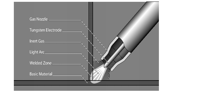
Inert gas welding procedures are the most frequently used methods of welding stainless steel parts together. With inert gas welding, a light arc burns between a non-melting tungsten electrode or a melting wire electrode and the work piece. In the process, an inert gas surrounds the weld point, deflects the ambient air and thus prevents chemical changes, such as oxidation in the pool crater.
A distinction is made between tungsten inert gas welding, metal inert gas welding and metal active gas welding (see figure 12).
|
Welding procedures |
|---|
|
|
MIG (metal inert gas)
|
|
MAG (metal active gas)
|
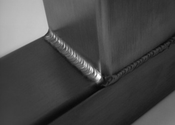
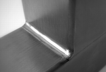
The difference between TIG and MIG/MAG is that with TIG welding, the welding gun contains a tungsten rod surrounded by inert gas, with the result that there is no scaling or fusion penetration on the welding seam. The welder applies the welding filler to the weld seam manually. TIG welding is mostly used in thinner walled areas up to a sheet thickness of 8 mm. An experienced welder can create a very clean and fine welding seam with this procedure. With MIG/MAG welding, the welding filler is also surrounded with gas. This time it is active gas. With MIG/MAG welding, in contrast to TIG welding, the welding filler is supplied automatically. Depending on the selected strength of the welding filler, the welds are also larger and thus rougher. MAG welding is recommended for sheet thicknesses of 10 mm and more.
Processing of welding seams
Welds within the product-contact parts are always ground flush with the material to the same surface quality specifications as the required surface finish (see also chapter 2 Surfaces).
The simplest way to process external welds (non-product-contact) is untreated, pickled and passivated. With chemical pickling, the parts to be pickled are dipped in pickling baths, depending on requirements, or the pickling agent is applied to the metal surfaces. At room temperature, the pickling agents act for a few minutes to a few hours and are then rinsed off with water. In order to give the welds a slightly neater appearance from the surface, they can be polished with a brush. The welds can be ground to obtain neat and easy to clean surfaces. This means that the butt welds are levelled to the level of the surrounding surface. Fillet welds are ground in the radius R > 3 mm. With fillet welds, more welding material must be applied when grinding bearing parts, so that there is sufficient material available after grinding to meet the required load bearing capacity.
The tendency to also grind the external welds is constantly increasing, in order to guarantee easy cleanability of the facility.
 |
 |
|
Figure 13 Untreated welding seam |
Figure 14 Ground welding seam |
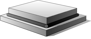
In addition, it must be ensured that the welds on external welding seams are always completely welded through. Partial seams are not permitted, as organisms can settle in the gaps and multiply (figure 15 and figure 16).
 |
 |
|
Figure 15 Continuous welding seam |
Figure 16 Partial seams |
4 Connections
4.1 Flange and quick release connections
The connection of pipes and adapters, and any method of connecting two components rigidly, is usually carried out through flange or quick release connections (Tri-Clamp connections). Bayonet connections are also possible, though these have largely been replaced with Tri-Clamp connections for hygienic reasons. The reason for this is that Tri-Clamp connections have prevailed due to the easier dismantling and improved hygienic design compared with bayonet connections.
Flange connections
Composition:
- 2 flange halves
- 1 flexible flat seal
- Screws, nuts and washers for connecting the flange halves
 |
 |
|
Figure 17 Flange connection |
Figure 18 Aseptic flange connection as per DIN 11864, Form A |
However, a flange connection does not necessarily have to be produced as per DIN (German industry standard). In the hygienic area in particular, flange connections are preferable for depressurised connections, with thinner flange thicknesses and fewer screw connections (number of screws distributed around the circumference) than with a comparable DIN implementation. The flexible connection between the flange halves often deviates slightly from the DIN standard of an injected flat seal. In the connection space between the two flange halves, either a flat seal is fitted flush with the inner tube, or O-ring connections, which also match with the inner tube diameter, are used.
The flange connections also deviate from the DIN connections in another respect. They usually have a mechanical centring device for the flange halves, in order to make it easier to fit the seal and to prevent damage to the seal during fitting in the flange connection.
Pressing the flange halves together by tightening the screws anchors the flexible seal securely in its seat and deflects it slightly into the product space, which results in a streamlined hygienic connection. There is also leeway for expansion of the seal in the event of temperature fluctuations. Flange connections without flexible seals can also be used up to a pipe diameter of 100 mm. These connections are called metallically sealing (figure 19).
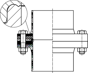 |
Figure 19 |
Difference between flange and quick release connections
(Tri-Clamp connection)
The difference between a flange and a quick release connection is essentially that a flange connection usually involves a rigid connection with screws and nuts as established in a DIN (Germany industrial standard). Such flange connections are available for various pressure stages. Accordingly, they can be very large and clumsy. A soft, flexible seal firmly connects the two halves of the flange to each other at the ribbed connection surfaces when the screws are tightened. This variant aims primarily to guarantee pressures.
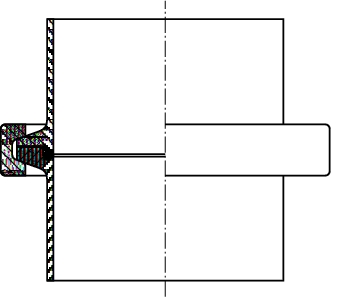
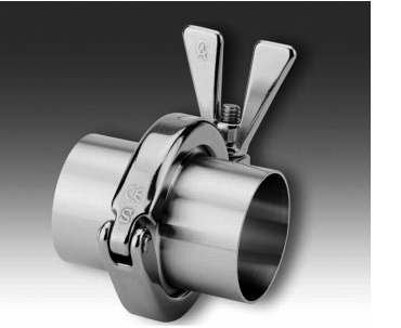
The Tri-Clamp connection also joins together two connection halves as a rigid connection. The difference between it and the flange connection is that there is a more flexible connection between the two connection halves. These quick release connections are available in a range of implementations and materials. In recent years, various manufacturers have worked very intensively and successfully on an optimal dead-volume-free quick release connection. The only disadvantage is that the sizes were designed primarily for pipes that transport liquids. Most of the Tri-Clamp connections shown below are available up to a size of 150 mm (figure 20 and figure 21).
 |
 |
|
Figure 20 |
Figure 21 |
Larger quick release connections are rarer and can now extend to a max. diameter of 300 mm. Quick release connections too can now be implemented in line with DIN standards. However, deviations may occur depending on the manufacturer. Therefore, it is important not to define the quick release connection as an interface between suppliers but to always order these quick release connections from one supplier and adapt them to the connection pipe of the connector.
Composition of a Tri-Clamp connection:
- Tri-Clamp connection halves with pipe set for welding onto the connection pipe
- Seal as shaped part or O-ring
- Clamp
The Tri-Clamp connection halves are usually not form fitting connections, but are provided with a groove for the moulded flat seal or O-ring seal. Due to the lack of a form fitting connection between the two connection halves, it is very difficult to assemble large quick release connections without additional assistance by one or two helpers (figure 22).
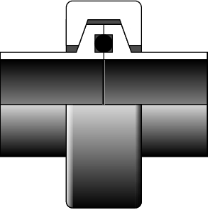 |
Figure 22 |
Assembly
During assembly, one person holds the part to be assembled, while a second helper, if necessary, checks that the seal is sitting securely and then closes the clamp securely around the connection. When tightening, it must be ensured that the seal does not slip and is not damaged during assembly. Unfortunately, improper installation of the seal is only ascertained during production, when dust escapes through the connection or liquid leaks during cleaning.
Installation of the seal is made all the more difficult if the flat seal used is made of silicone. In this case, installation with a diameter of >200 mm is only possible if more than two people are involved, as the very flexible flat seal must repeatedly be pushed back into the position prescribed for the seal before the clamp can be secured.
A very soft and flexible seal is, however, a prerequisite for a closed and leak-tight connection. There are also PTFE (Polytetrafluorethylene - Teflon) seals with a soft core. These are easier to fit and are also not so easily damaged during installation. However, they have the disadvantage that the connection is not dust-tight or liquid-tight during cleaning. With PTFE seals, the choice of clamp must be given particular attention.
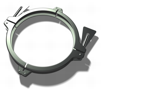
Clamps
Here, two half clamps should be used, which can be tensioned on both sides with a tool in order to produce a more secure connection (figure 23).
 |
The following must be noted for quick release connection halves:
- Quick release connection halves usually have a weld-on pipe for connection with an extension tube or another connection. It must be ensured that the welding pipe is long enough not to transfer too high a heat influence around the sealing surfaces during connection welding, because warping caused by the welding heat means it is no longer possible to achieve tightness in the connection.
- Materials: Quick release connections are today nearly exclusively made from stainless steel material 1.4435 or even 1.4404 or in accordance with USA standard (ASTM 316L) (see also chapter 3 Material: stainless steel). It is also possible to obtain the entire item made of Hastelloy C22, which is significantly more expensive.
Note: In part, the product-contact surfaces (product-contact surfaces come into direct contact with the product or the solvent to be cleaned) are Halar or PTFE coated, in order to save costs for expensive Hastelloy. Halar and PTFE are very resistant plastic surfaces (see also chapter 3 Material: stainless steel), which are applied to the stainless steel surfaces. In this case, it must be ensured that around 0.2-0.5 mm of material is applied. Sharp edges must be avoided on the connection parts and replaced with radii before application. In the end, making a coated quick release connection leak-tight is so time-consuming that there is no price advantage over Hastelloy.
Seals
When selecting the seal between the connection halves to be connected, please note the following:
- Differences in the shape: the following examples show different shapes of seal. The best connection has proven to be an O-ring connection which is flush with the inner tube. This is, however, only available up to a size of DN 100. For anything bigger than DN 100, many quick release connections have an O-ring connection in the centre of the connection halves, which means an absolute GMP deficiency in terms of hygienic (figure 22). A positive-fitting flat seal is better in this case (figure 24).
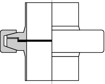
Figure 24 Flat seal
- Material of the seal: the most frequently used selection criterion for the sealant is its resistance to solvents. Be it because a product contains solvents (e.g. after the centrifuge) or because solvents are used for cleaning. The second most frequent reason is FDA-compliant (see extract from the material list) or electrically conductive material. Another selection criterion might be flexibility, in order to realise more leak-tight connections, for example (figure 25).
Figure 25 Extract from a list of resistances against solvents (source: ESSKA Maschinen Vertriebs GmbH)
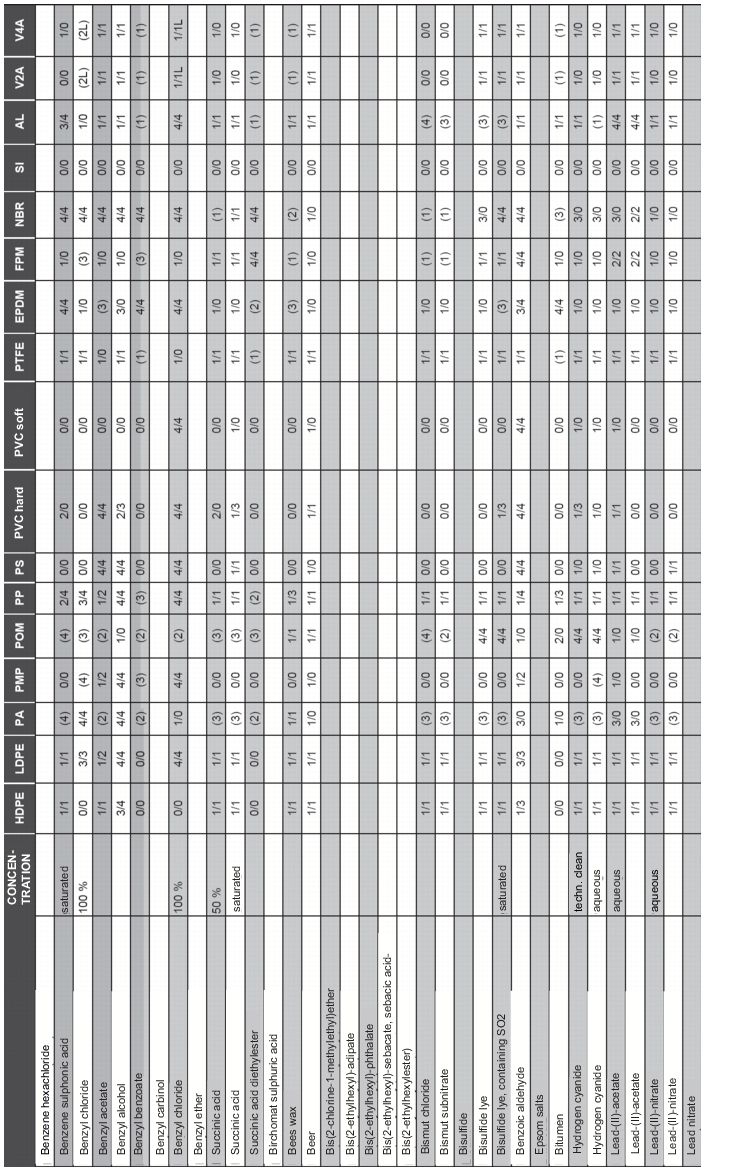
The most flexible connection is a seal made of silicone, followed by EPDM (ethylene-propylene dien rubber) and Viton, which are still flexible and are also more resistant to solvents. A very high resistance to most solvents can also be achieved with a PTFE seal (polytetrafluorethylene) on flat or shaped connections. With PTFE seals, it should be ensured that the sheath is made of PTFE and the core of a flexible material (e.g. silicone), in order to achieve better tightness of the connection. For connections with an O-ring seal, O-rings coated in PEP (perfluorethylenepropylene) are often used. These also consist of a soft core and a thin FEP sheath, which is resistant to the most frequently used solvents. Another material with the best resistance to nearly all solvents is Kalretz. However, Kalretz is a very rigid sealant material and can therefore only be used in certain cases. It is also barely economical due to its high manufacturing costs.
4.2 Flexible connections
In addition to rigid connections, flexible connections are also used. Flexible connections are required for uncoupling a balance, for example, or for uncoupling moving, vibrating parts from their rigid connections. Flexible connections can be produced in a wide range of shapes and materials. However, it must be ensured that the connections to the rigid connection are either easy to undo for cleaning or are suitable for CIP in a hygienic design (chapter 4.I CIP (Cleaning in Place)). There are also different implementations for the materials. The most frequently used material is silicone. The reason for this is that it is so flexible compared with the other materials. It is therefore used for uncoupling balance. Other materials include EPDM, NBR, Viton, PTFE and Kalretz. While EPDM, NBR and Viton are still considered to be flexible and can be used for balance uncoupling in certain conditions, PTFE and Kalretz are more rigid. With PTFE, more flexible materials like silicone can be coated in a thin layer of PTFE or thin PTFE films can be used, which in turn creates a flexible connection. EPDM, NBR, Viton, PTFE and Kalretz are resistant to current solvents such as acetone and toluene.
The above-mentioned materials are available in food or FDA-compliant implementations in light quality. If the plastics come into contact with solids which have a risk of exploding dust, the plastics must have additives that make them conductive. The colour of this plastic ranges from grey to black and it is only available in a food or FDA-compliant quality with limitations. To guarantee the use of light plastics when handling critical products, the product-contact side should be made inert in a closed process with nitrogen.
Examples of different flexible connections
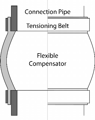
Collar for adaptation of the same or different containers to one connection piece.
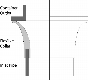
This variant is an open pipe with a collar or tension band. Both systems shown fit flush with the connection container. With variant 1 (figure 26), a connection pipe penetrates the flexible collar. The connection is dust and water-tight.
 |
 |
|
Figure 26 |
Figure 27 |
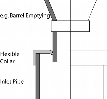
With variant 2 (figure 27), a connection flange, which is secured to the container outlet, is pressed onto the flexible collar. This connection enables quick and easy connection of very large containers. However, it usually only has limited dust and water-tightness. Slight unevennesses on the connection flange result in small gaps through which product can escape.
Flexible collar with two connection ends (figure 28). This specially produced collar for connecting two pipes is set apart by its material offset on the connection pipe. This means the collar is nearly flush with the material in the product-contact area. The interior of the connection can therefore be cleaned more easily. The collar is secured with tension bands at the inlet and outlet. This guarantees a dust-free connection. Disadvantages: The bulge in the collar means product can become trapped in the trough.
 |
 |
|
Figure 28 Flexible |
Figure 29 Flexible collar with balance uncoupling |
Flexible collar with Tri-Clamp connections
This specially produced collar can be very easily integrated as an intermediate piece in a quick release connection (Tri-Clamp connection, see screw connection and quick release connection in chapter 4 Connections). The connection is CIP (Cleaning in Place) capable and is extremely hygienic due to its dead-volume-free implementation.
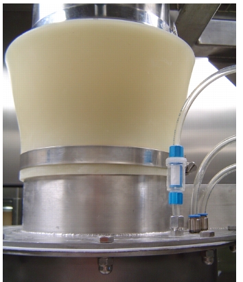
Flexible collar for balance uncoupling (figure 29)
When uncoupling a balance via a flexible collar, the design of the collar is crucial. The collar shown in figure 29 is distinguished on the one hand by its optimal balance uncoupling via a horizontal and vertical connection, and on the other hand by the fact that it is easy to clean.
4.3 Screw connections
In contrast to a welded connection, a screw connection is a fixed but detachable connection. This type of connection is required if it is necessary to be able to disassemble parts for maintenance and repair, or if the parts are very large and can only be brought into the room when dismantled. The parts are reassembled in the room and connected to each other via a fixed screw connection. A screw connection can also bear very high forces and torques.
Another reason for using a screw connection is the safety of the connection. In the pharmaceuticals and API area in particular, quick connections are often used for easy cleaning of the facility (see also Quick release connections in chapter 4 Connections). In many cases, a quick release connection can be opened without a tool. The operator can therefore access the inside of a container or other systems at any time. This is not always desirable and can also be hazardous if, for example, there is a moving part inside. To protect this area from undesired access, a quick connection is sometimes implemented as a screw connection at a certain position. This single screw connection is quicker to release with a tool than if the operator had to disassemble an entire flange with screw connections. The remaining connection is opened via the quick release connection.
A screw connection is therefore not a quick release connection. A tool is required to open a screw connection and close it again. A screw connection consists of two connection components that are connected with a screw, washer and nut. The classic screw connection consists of a screw specified in accordance with DIN (German industrial standard). Depending on the requirements, various strengths, lengths and designs of screw can be used. The connection is tightened by turning the screw in a thread. The thread is located either in the counterplate or in a nut. This is used if the connection is made through two fastening elements without a thread.
The following designs are suitable as sanitation connections (figure 30 to figure 33).
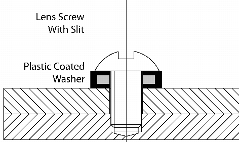 |
Figure 30 |
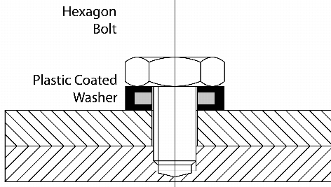 |
Figure 31 |
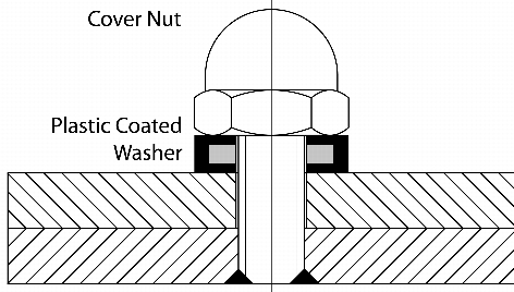 |
Figure 32 |
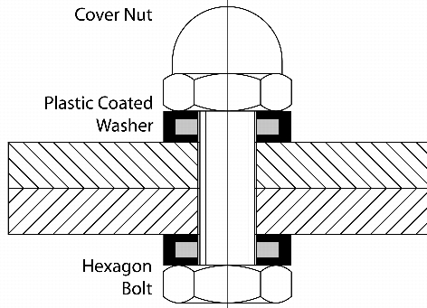 |
Figure 33 |
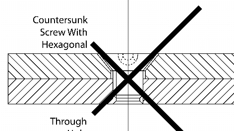 |
Figure 34 |
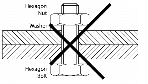 |
Figure 35 |
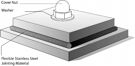 |
Figure 36 |
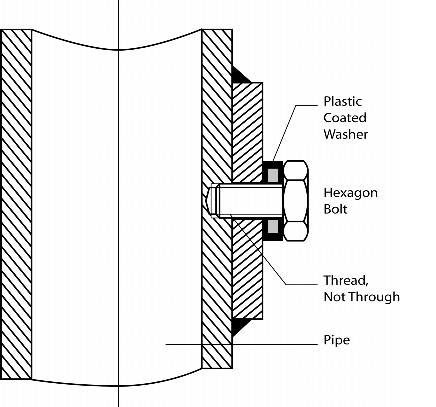 |
Figure 37 |
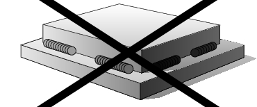
Figure 34 and figure 35, however, are unsuitable as they contain dead space and protruding threads, which cannot be cleaned, or can only be cleaned with difficulty.
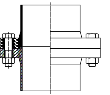
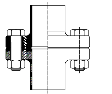
If the screw connection is to be unscrewed rarely, it is recommended to seal the transitions from one connection part to the other with a flexible connection (figure 36), which can also be removed again.
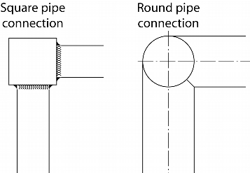
In particular, it must be ensured that a screw connection to a pipe (square, round, rectangular pipe, etc.), does not enter the inside of the pipe. When undoing the screw connection, this would create an open system from a contaminated area within the pipe to the clean area outside the pipe. Therefore, a plate or reinforcement should be welded onto the pipe in order to be able to attach a blind hole with a thread, so that the contaminated area within the pipe remains unopened (figure 37).
It should also be ensured that the washers between the screw head and the connection plate have a flexible surface. This flexible surface seals the space inside the screw connection so that no contamination can occur here either.
5 Hoists and roller conveyors
5.1 Hoists
Lifting columns have become established in the hygienic area, as alternative hoists, such as chain hoists, fork-lift trucks or caterpillars can only be encapsulated with limitation.
But there are also different designs of lifting columns. In general, all lifting columns in the external area are covered in stainless steel sheets or have stainless steel profiles.
A hygienic lifting column is distinguished by its inner guide and the sealing of the centring slide as well as the cable duct for the components to be actuated. The centring guides for the centring slide should always be inside the lifting column. Particular attention should be paid to the sealing of the centring slide on the lifting column, as this seales the lifting movement of the centring slide. The reason for this is the different variants that also protect the inner workings of a lifting column against contamination from the environment. In most cases, a plastic or stainless steel band is used as the cover, which is pulled through the back of the centring slide during the lifting movement of the lifting slide.
The design is superficially very good, but is not tight through to the inside of the lifting column. The plastic band can be removed by hand and intervention in the inside of the lifting column is possible. Nor does the cover band rule out contamination of the inner parts. A much more elegant and better design involves stainless steel cover bands or rollers, which close off the centring slide from the inside of the lifting column. These stainless steel rollers can be sealed in integrated guides, so that the lifting column can also be installed on the clean room wall.
In the event of installation in a clean room (wall installation), the back wall can be opened at the rear of the lifting column (in the services area outside the clean room) for maintenance and repair work, via quick-flange connections as on electrical switch cabinets (safety locks with special tool). This reduces the interruption to the use of the facility during maintenance work compared with the disruption caused by work that would have to be carried out inside the clean room.
General requirements: A lifting column should always be designed so that the external parts are smooth and easy to clean. The electrical cables and pneumatic tubes should be routed inside the lifting column.
It is easier to lay the cables inside the lifting column and this also ensures that the outside of the lifting column has a better design. If the cables are to be installed externally, it must be ensured that they are routed in an enclosed tube, the outer surface of which must be cleaned.
If the lifting column is set up in an area that is classified as at high risk of explosion, the closed tube must also be permitted for this area. This is an absolute requirement in accordance with ATEX (Atmosphere Explosible Directive a4/9/EC - Use of facilities in explosive environment).
External and internal surfaces: In most installations, the external surfaces of lifting columns are made of stainless steel and the inner parts are partially or totally of carbon steel. As there are moving parts inside the lifting column or an aggressive atmosphere in the environment which can cause temporary or permanent use of solvents, rust may start to form inside the lifting column. A better design is a lifting column made completely of stainless steel, even if this means a higher investment.
Part of the lifting column must not only execute a lifting movement, but must also pivot the lifting column from one to several other positions. The cover of the wheel flange must also be closed. The wheel flange is located near the floor where wet cleaning is often carried out. The wheel flange cover should be sealed to avoid the entry of spray water.
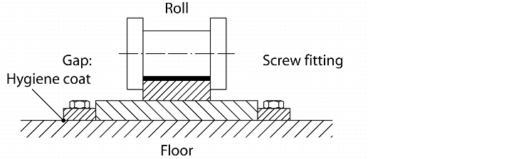
5.2 Roller conveyors
Roller conveyors are usually used as a delivery transport system or removal transport system for drums, fibre drums and other containers. A prerequisite is that the containers can be transported on rollers. A roller conveyor may also be necessary to make the operator's work easier, as they would otherwise have to transport the full and empty containers by hand. With the supply transport system, the empty containers are stacked up and moved under the filling system. In the filling position, there is usually also a short roller conveyor section. The removal transport system for the full containers buffers them before the containers are palletised. Roller conveyors are available in various implementations.
Manual roller conveyor
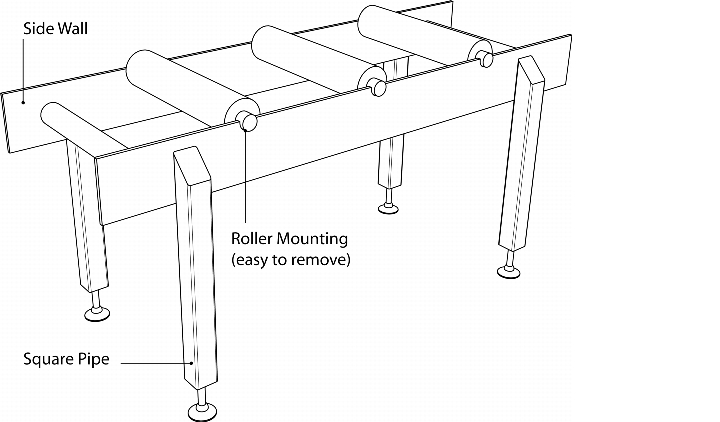 |
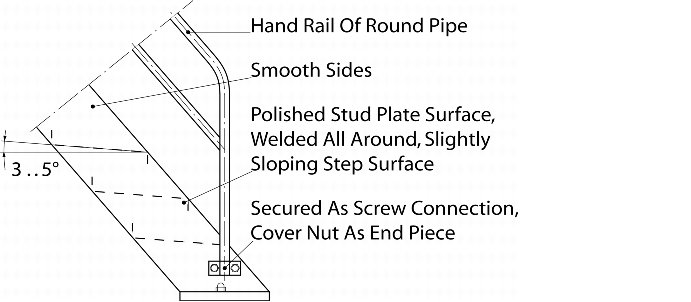
The simplest variant is a roller conveyor without a drive. With this type of design, the containers must be moved by hand or are transported by gravity. (The roller conveyor has a slight slope of around 5°.) With a manual roller conveyor, the facility's performance does not play a significant role. The advantage of this system is the design of the roller conveyor. It can be simple, which also makes the conveyor easier to clean. The side walls can be made of vertical plates which are connected by round tubes. The feet are also a closed square tube construction, which are sloping at the top end and closed. The roller conveyor support is designed so that the rollers are easy to remove for cleaning purposes (figure 38).
Driven roller conveyor
The other variant of the roller conveyor is the driven roller conveyor. The driven roller conveyors have the advantage over manual roller conveyors that performance is increased through the automation. However, automatic roller conveyors lose the advantage of easy cleaning. On driven roller conveyors, the walls are fitted in a sandwich construction, in order to accommodate the roller to roller drive elements in the spaces. The drive elements can be chain wheels with chains or a V-belt connection.
The V-belt connection is always preferred to the connection chain, as the V-belt does not have to be lubricated and is also easier to clean. The arrangement of the roller conveyors and their accessories depends on the task. For example, to save space, the containers can be stacked one on top of the other as shown in figure 39.
 |
The empty containers are buffered in the top area and transported to the bottom area as required, via a lifting device, where they are then automatically brought to the filling position. If the roller conveyors are in a controlled area (in a clean room), the empty and full containers must be brought through a material lock
In the locks, there may also be an air nozzle to clean the containers before they enter the clean room. Other additional equipment includes systems for palletising the containers, as well as vacuum lifters which lift the containers via suckers and allowing an operator to then set them on pallets. A pallet robot automatically sets the cover on the container, positions the container on the pallet and wraps the entire pallet in film. A fully automatic conveyor and palletising system is only worth while with high performance rates (more than 40 barrels per hour).
6 Pneumatic conveyor system
The use of pneumatic conveyor systems requires particular attention to the cleanability of the system. As a general rule, pneumatic conveyor systems are used wherever filling or emptying of a product is not possible via gravity. This can be the case if there is only limited space above the container or process system to be filled or below the container process system to be emptied. A pneumatic conveyor system may also be used for filling a reactor during API production. On the one hand for more gentle and controlled product feeding (quantity dosing) and on the other hand, as a lock from a depressurised container emptying system to a pressurised container, in which a chemical reaction takes place. The prerequisite is that the pneumatic conveyor system can be used as a lock.
Pneumatic conveyors are distinguished into pressurised conveyors and vacuum conveyors. Vacuum conveyor are usually used to transport products up to a distance of around 50 m from the feeding station to the separator. If the delivery distance of is greater than 50 m, pressurised conveyors are usually used. These conveyor sections are less likely in API production or in drug product manufacturing and are not to be advocated due to hygienic reasons.
There are two different kinds of vacuum conveyor system that can be used. First, a vacuum conveyor with a separator, and second, a powder transport system (PTS, see chapter 4.J.11 Containment on equipment).
6.1 Vacuum conveyor with separator
Dilute-phase conveyor system
Vacuum conveyors working with the dilute phase (little product with a high volume of air) usually have large separators which contain the filter medium for separating the product before the vacuum generator (figure 40).
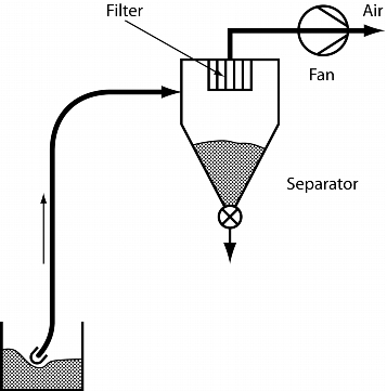 |
Figure 40 Vacuum conveyor system with separator |
Due to their size and filter surfaces, these systems are only suitable for use in sanitation if they are mono-production system or if the filters are easy to change and the system easy to clean. Another weakness of this system is the separation of the product during delivery. Due to the low product load during transport and the high delivery speed, the small, light particles are delivered more quickly than the larger, heavy particles. The abrasion and mechanical stress of the product during delivery are high. For products with a low ignition energy, this can even mean that they have to be transported with nitrogen.
Cleaning of these systems is usually very time-consuming and requires high manual effort. Preliminary cleaning by means of WIP (Washing in Place) is possible.
6.2 Powder transport system (PTS)
Dense-phase conveyor system
The powder transport system (PTS, see chapter 4.J.11 Containment on equipment) is also a system that works with a vacuum. The difference between this and a conventional system is that the PTS system works with a very high vacuum. This high vacuum means the product to be conveyed is delivered in a pipe or preferably a tube system with very high loads. Due to the high load and the lower air volume, the separator only has a small filter surface. The filter used is a membrane in the diameter of the separator. At around 6-8 m/sec, the delivery speed of the PTS systems is about a quarter the speed of a normal conveyor system. This also makes it easier to deliver very sensitive products with a minimum ignition energy of <1 mJ without having to add nitrogen during delivery. Separation of the product is prevented by the dense loads during delivery.
The product is added to the containers or reactor in a nitrogen atmosphere. To this end, the product delivered in air is placed under a very high vacuum in the separator and evacuated from the oxygen. Then the separator is filled with nitrogen and the outlet flap to the reactor is opened. The advantage is that the addition of nitrogen significantly reduces the oxygen concentration in the reactor.
The system can also be cleaned with validation by integrating a CIP system (Cleaning in Place) and a liquid separator. With a comparable delivery rate, the PTS system is about half the size of a conventional delivery system.
7 Dosing systems
Dosing systems are used to empty or fill a predefined quantity. This can be a blend of different raw materials or a single dose of the same product. A dosing system is also used to create portions in smaller containers or even to empty the product into a reaction vessel.
The dosing system is fitted between the pack, container or process equipment to be emptied and the pack, container or process equipment to be filled.
There are many kinds of dosing systems. This is due to the flow behaviour of the products, which varies from free flowing to sticky and splurging. Room heights, facility offset and metering accuracy also play a role in the selection of a dosing system.
7.1 Vibration dosing device
A vibration dosing device is usually suitable for easy flowing products and granulates.
Advantage of a vibration dosing channel: There are no attachments in the dosing system. A vibration dosing device consists of a dosing pipe or dosing feeder, usually with a round inlet and outlet. The drive is located beneath the dosing system and can be a magnetic drive or a pneumatic drive, which transfers vibrations to the dosing system and thus causes the product to flow. The product flow is reduced or increased by setting different frequencies on a magnetic drive or different pressures on a pneumatic drive, which enables dosing to a predefined value.
7.2 Dosing screw
A dosing screw can convey and dose a wider range of products than a vibration dosing device. These can range from very free flowing to sticky, heavy flowing products. The reason for this is that a dosing screw is a forced delivery system. Once the product has been added to the screw workings, it is usually then also conveyed. The dosing system consists of an external pipe, a screw, sealing flange at the ends with bearing and shaft feedthrough as well as a drive. By actuating the drive via frequency regulation, the speed of the screw can be increased or reduced. The dosing screw is always cleaned manually by dismantling the dosing screw. The dosing screw can be pre-cleaned when fully installed, but dismantling is unavoidable for complete cleaning. Easier dismantling can be guaranteed through the use of quick connections.
7.3 Slite dosing gate (knife-gate).
The slite dosing gate is used as a so-called in-line dosing system. In-line means that there is no offset between the area to be emptied and the area to be filled, as with the dosing screw, for example. The products are added to the dosing gate by means of gravity. The dosing gate consists of a housing and a sliding plate, which is actuated via a drive. For example, it might be a pneumatic cylinder which opens and closes the gate. To make the system into a dosing system, the pneumatic cylinder is fitted with a position sensor. This enables the dosing control to open or close the gate in different positions. The cross-section through which the product can flow is regulated in this way and the product is dosed. When selecting a slite dosing gate, it is important to note that it does not have any dead space and is quickly dismantled for cleaning purposes.
In the case of thicky, heavy flowing products, a product supply system must be added upstream of the dosing gate. The product supply system keeps the product moving and supplies it continuously to the gate. This means a high metering accuracy can be achieved even when dosing heavy flowing products.
7.4 Flexidos dosing system
The Flexidos dosing system, like the site dosing gate, is an in-line dosing system but with a dosing slit in the product-contact area. This dosing slit is opened externally by two synchronously controlled dosing pusher. A closing spring in the dosing system pulls the dosing slit together again after the dosing pusher have released the dosing system. The dosing pusher are moved by the dosing control and open the dosing slit according to the dosing output and accuracy. With the Flexidos dosing system, the slowest flowing products can be dosed with maximum accuracy <1g. The dosing system is easy to change and clean. As with the dosing gate, the Flexidos also needs a product supply system for heavy flowing products.
7.5 Transbatch feeder
The transbatch feeder is a combination of pneumatic convegor system and a vibration dosing device. The pneumatic conveyor sucks the product into the separator which is attached to the vibration dosing device. The vibration dosing device conveys the product, which has been loosened by the pneumatic conveyor, into the pack or container to be dosed.
8 Platforms and stands
Stands or platforms are required for the implementation, operation and maintenance a solids system. The stands hold adapters or components. The platforms make it easier for the operator or service staff to access the facilities. Here too, hygienic design is important.
8.1 Platforms
The following points should be taken into account when designing a platform:
- The steps of the stairs should be added in two side walls (figure 41).
Figure 41 Stairs, platform
- The walls should be made of thick-walled smooth sheets.
- The steps should be made of polished stud plate surfaces, which are edged at both ends in the opposite direction.
- The step surfaces should be slightly sloping so that the cleaning fluid can flow off more easily during cleaning.
- The hand rail on the stairs should be made of round piping, which is closed at the ends.
- The mounting closure on the rails should be implemented with cover nuts.
- The substructure of an operating platform should be made of a closed square pipe or round pipe construction.
- The platform surface, like the steps, should be made of polished stud plate.
- The foot edge should be edged on all sides and the joints at the corners should then be welded.
- The bearing surfaces on the platform should, like the steps, by slightly sloping, so that the cleaning fluid can flow off more easily here during cleaning and no puddles form or liquid residues remain.
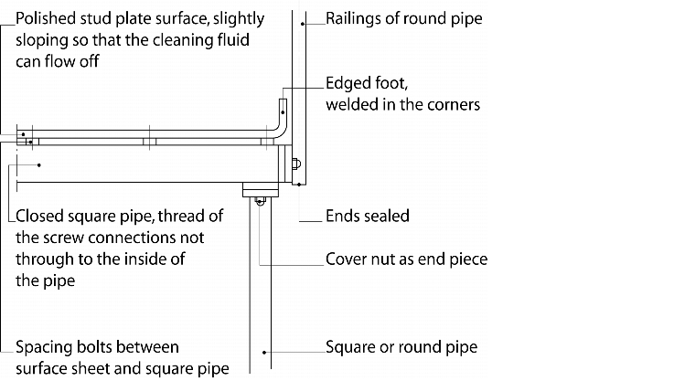
There should be spacer bolts between the square pipe or round pipe construction and the stud plate surface (figure 42) so that the space between can be more easily cleaned.
 |
If the stud plate surface is welded directly onto the substructure, (figure 43), it must be guaranteed that the stud plate is welded right through. If this is not possible, due to excess warping of the platforms due to the long welds, the spaces between the individual welding seams must be filled with a flexible stainless steel jointing medium. The thread ends on screw connections on the substructure should also be sealed with a cover nut.
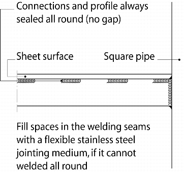 |
Figure 43 |
8.2 Stands
The question of which profile to choose for stands and the substructure of platforms cannot be answered in general. Round pipes certainly have an advantage in terms of cleaning. However, they are more costly to manufacture. When using square pipes, there is more available horizontal bearing surface on which the product or dust can be deposited, but this surface is too small to justify the higher costs of a round pipe construction. A cleanly processed stand or the substructure of a frame produced from square piping is in any case suitable for installation in a controlled area (figure 44).
What has to be avoided in all events is open profiles such as U-tubes or similar.
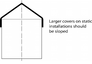
Sloping covers (figure 45) should be used. On the one hand, this makes the surfaces easier to inspect for impurities, if they are in an elevated position. On the other hand, the cleaning fluid can flow off more easily.
 |
 |
|
Figure 44 Connection of profiles |
Figure 45 Covers |
9 Clean room installations
For clean room installations, attention should be paid not only to the product-contact surfaces, but also to the overall design of the external parts. The surfaces in the clean room must be easy to clean not only on the product side, but also on the external surfaces. In order to enable cleaning of the exterior, the surfaces, cable ducts and attachments should be designed specifically.
9.1 Rail design
Example 1 (figure 46 and figure 47): Rails attached to a Pharma Terrazzo.
 |
Figure 46 Rail guide - unfavourable due to contamination and tripping points |
 |
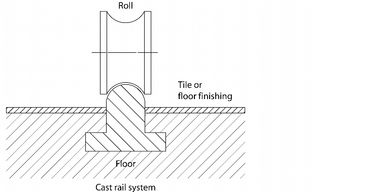
Example 2 (figure 48 and figure 49): Rails integrated in the hexagon tiled floor
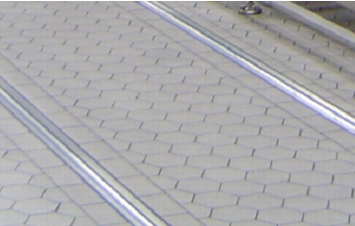 |
Figure 48 Rail system integrated in the floor |
 |
Both systems initially appear to be hygienic implementations. The difference between the two systems is the implementation and attachment of the rails. In example 1, the rails are attached to the floor and screwed down. This is initially a very attractive, cost-effective and quick solution. In practice, however, the connection at the transition from the rail to the flooring will rip and contamination will build up in the chinks, thus increasing the gaps. After a foreseeable amount of time, there will be a GMP deficiency, which can only be improved with great difficulty. A further disadvantage is the greater risk of tripping.
The best solution is example 2. Here, a special rail design is integrated in the floor, before the hexagonal tiles are laid. The profile is integrated flush with the surface, making a semicircular sphere with the neighbouring flooring. This shape is optimal as a track for the carriage and is also easy to clean due to its geometric shape.
The disadvantage is that the installation costs are higher than with the first example. But the follow-up costs for maintenance and repair are much lower.
The choice of hexagonal tiles was also a good decision, as the tiles are more robust and durable and still look like new after ten years.
9.2 Control panels
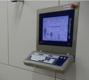
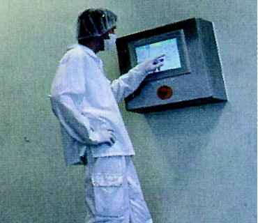
If possible, installation flush with the surface of the clean room wall is always recommended (figure 50).
 |
 |
|
Figure 50 |
Figure 51 |
Installation of the control panel with the front flush with the wall means there are no surfaces as shown in figure 51 which require cleaning. In addition, the operating keypad has no surfaces on which anything can be deposited. The cables to the operating panel should in any case be routed and laid within the clean room wall (sandwich construction) so that no additional pipes for cable ducts are required in the clean room.
9.3 Cable ducts
Cables are required in a clean room to control valves, motors, sensor, etc. Flexible lines are also required for compressed air-operated facility components. Most errors are made when laying the connections or if, for cost reasons, clean room compliant installation is not used.
 |
 |
|
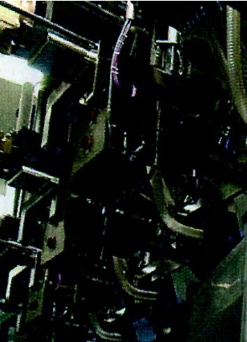
Figure 52 Unfavourable cable routing |
|
As shown in figure 52, cables or pneumatic tubes are bundled together here via cable ties and openly laid in the grating channels or half open in pipes. This has the disadvantage that the external parts cannot be cleaned. Product dust which collects between the tubes is difficult to remove through manual separation of the tubes or cables. The half open routing of cables and tubes (necessary to hold tubes or cables over a long distance) in open pipes increases the cleaning problem for facility components. If unavoidable, such cable ducts should be laid vertically and the ends should be sealed after the cables have been laid. As shown in figure 52 , the pipes are laid horizontally, which leads to a GMP deficiency. Product dust, which can rarely be avoided when handling solids, collects in the pipes. The external surfaces of the pipes can be cleaned, but the impurities remain in the pipe.
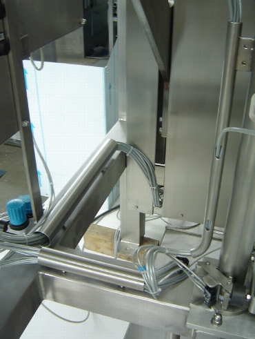
A closed cable system should always be used in clean room installations or in controlled rooms. This type of system contains the cable duct within closed square pipes used as mounting stands or in round pipes that are only used for holding cables. The design of the overall facility must be thought out in detail, as the openings at the cable inlets and outlets must be taken into account and provided for in the detailed design (figure 53 to figure 55).
 |
|
 |
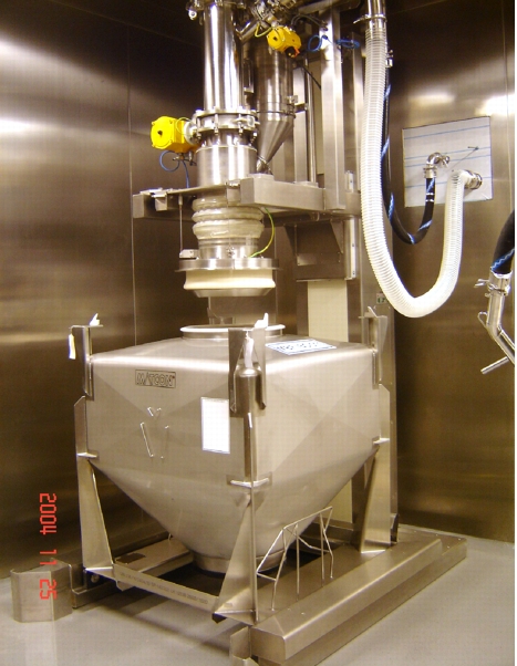 |
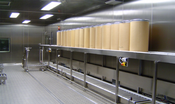
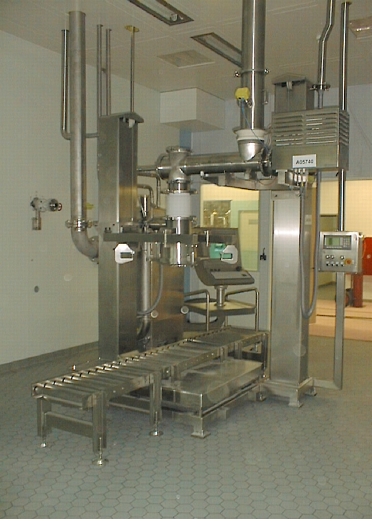
Figure 55 Example of a clean room installation - container filling |
The cables to the consumer should take the shortest route from the cable outlet to the consumer (around 300-400 mm). The cables should also exit the pipe via individual connections, so that each cable can be cleaned independently. The cable outlet is also the entrance from the black area to the white area in the clean room and, accordingly, must be leak-tight. Therefore, the cable feed into the pipe should be implemented with a closed system such as a PG screw fitting for cables or a quick screw fitting for hoses.
In any case, pneumatic boxes with the valves should be set up outside the clean room and the hoses then routed into the clean room bundled together and enclosed.
Compressed air should never be blown out in the clean rooms through quick ventilation valves on installed pneumatic cylinders. The air should be routed out of the clean room to the services area.
|
Summary The hygenic design of a solids facility is determined by various factors, such as its use in a mono or multiple purpose plant or by the dosing system used. In any case, the design phase for a solids facility should involve an element of common sense. The design criteria mentioned in this article should be selected and described in the user requirements for the solids facility. |
