|
Here you will find answers to the following questions:
|
1 Significance
The significance of containment in the pharmaceutical and API area is understood as health protection for operators and as product protection. Drugs or APIs can be dispensed in liquid or solid dosage forms. This chapter does not deal with liquids in further detail, as closed systems are better used in this area. In the API area, these are starting materials, intermediate products from the centrifuges or powders after drying. All have in common that dust is released in varying concentrations and particle sizes during production. If handled without special protection, this dust is inhaled by the operator and can enter the bloodstream via the respiratory tract. Products can also be absorbed via the eyes or skin. Particularly with highly potent drug substances, this working method can lead to short-term or long-term damage to the employee's health or can damage the genetic material. For this reason in particular, it is important to contain the product where it is manufactured - from the first step of the process through to packaging in capsules or blisters.
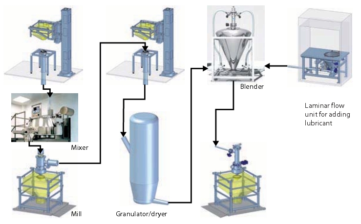
So far, extra attention is paid to full protection of the operator during the production of highly active APIs and drugs (see figure 1) or the facilities are installed in isolators or laminar flow units (secondary containment).
1.1 Use of laminar flow units
The use of systems engineering in laminar flow units results in the undesired side effect that the interior of the laminar flow unit becomes contaminated. When the product or batch is changed, the laminar flow unit must be cleaned, which in turn can be problematic for the health of the operator if the laminar flow unit has to be dismantled or opened for cleaning. Furthermore, each container discharged from the unit, as well as the personnel, must be cleaned (decontaminated). It is recommended that swab tests be carried out on the operator, in addition to regular particle monitoring, in order to ensure that the operator's clothing has not become contaminated.
1.2 Working in the full protection suit
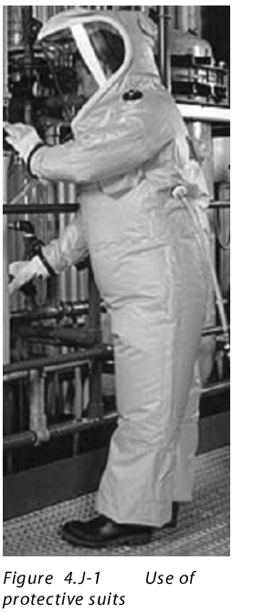 If the entire work process is set up without containment systems, work must be performed in a full protection suit, depending on the potency of the medicinal product or API. The working area must be isolated accordingly. Access by the operator must be via special locks.
Putting on a protective suit is a time-consuming procedure for the user. The operator must leave the room for a break after two hours. First, the protective suit must be decontaminated to prevent transfer of the product from the isolated area. For health and safety reasons, there must always be two people in the room, which means increased personnel costs. A further person is located in the neighbouring room to complete the records. To enable this, the operators have radio links with each other and must confirm the values with each other to avoid errors. If an electronic system is established and validated, the records can also be filled in by the personnel in the room.
When using protective suits, the following legal principle should be taken into account, in accordance with EU Directive 89/391 EEC Introduction of measures to encourage improvements in the safety and health of workers at work. This directive explicitly refers to containment systems with the following wording: "Giving collective protective measures priority over individual protective measures." The reason for this is that most personal protection measures have failed, either through small tears in the suits, which go unnoticed, or through incorrect wearing of the protective suits. To counteract this, systems have since been developed, and also successfully implemented, to contain the product in a constantly closed process - even during transportation in intermediate containers, such as containers (IBC - Intermediate Bulk Container), Big Bags (FIBC - Flexible Intermediate Bulk Container) and drums. This has the advantage that the operator can move without taking particular precautions, and it also rules out cross contamination.
2 Definition of terms
Containment: Process of containing a biological agent or other material within a defined space.
Primary containment: A containment system that prevents the escape of a biological agent into the immediate working environment. This includes the use of closed containers or biological safety workstations together with safe working procedures.
Secondary containment: A containment system that prevents the escape of a biological agent externally or into other working environments. This includes the use of premises with special ventilation and the availability of locks and/or sterilisers for removing materials together with safe working procedures. In numerous cases, this can increase the efficacy of the primary containment.
Containment area: An area designed and operated (and equipped with suitable ventilation and filtration systems) in such a way as to prevent the contamination of the environment by biological agents from the area.
3 Containment grades of products
The requirements are specific for each individual product, and must therefore be defined for each product. Different grading systems exist. In Germany, the residue limits are defined by the AGW (workplace limit value). Internationally, grades are recognised in accordance with the OEL (Occupational Exposure Limit). The pharmaceutical industry classifies its products and active ingredients according to different bands (OEBs, Occupational Exposure Bands).
OEBs (Occupational Exposure Bands): These bands consider the toxicology of the pure substance. The aim is to provide a system categorisation that can be used to select a suitable production facility and working procedure for a product.
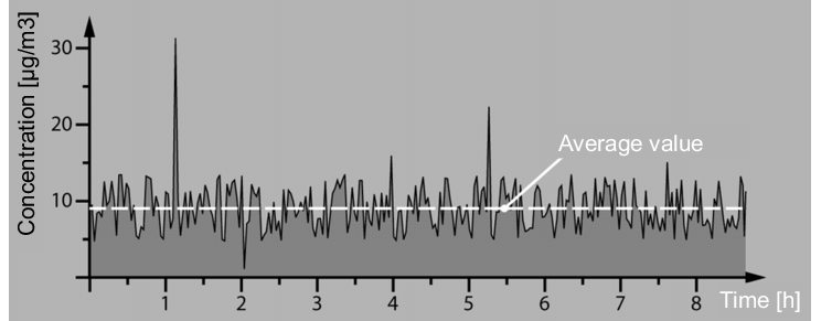
The OEL (Occupational Exposure Limit) defines an average concentration load of a drug or API measured over a particular time (TWA - Time Waiting Average). The measurement is carried out in the employee's breathing area over a period of eight hours (40 hour week). The term OEL comes from the pharmaceutical industry, where internal occupational exposure limits have been calculated for a long time without being regulated by the authorities.
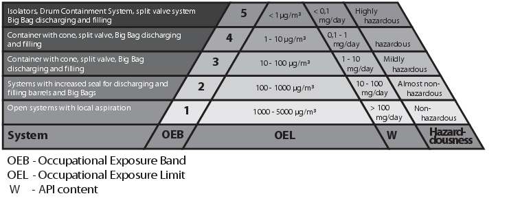 |
Grading in accordance with the table from OEL1 to OEL5 (see figure 2) must be defined according to the toxicity and the potency of the product. While open systems with local aspiration are used in the OEL1 area, the systems must become increasingly closed higher up the pyramid. OEL5 products can only be processed using special equipment (see chapter 7 Containment systems for filling and emptying drums).
The following special feature should also be noted when selecting the facilities: The containment grade deals with the particles in the air, not the product build-up on the surfaces. It is absolutely possible for a system to be graded as a containment system and yet still have product caking on the external surfaces at the containment interfaces after system separation. (This refers to the separation from one unit to a different unit, with the containment system being separated in between.) Compliance with OEL4 or higher can still be achieved nonetheless. Provided the product remains on the surface or only a small number of particles escape into the air when the product falls, the required value is, on average, not exceeded. This is permissible but not desirable, as the cleanliness of the facility in this case is highly user-dependent. It is recommended to perform swab tests at interfaces and on surfaces in order to determine the level of product residue on the surfaces.
The residue limits are defined using company-specific calculations provided by manufacturers of active pharmaceutical ingredients and medicinal products. Among other factors, this calculation takes into account the toxicity, carcinogenicity, mutagenic properties or fertility-damaging effects of the substances. If the residues exceed the residue limit, the surfaces must be cleaned with appropriate methods before leaving the room in order to prevent carry-over or cross-contamination.
The following categorisation systems should also be mentioned:
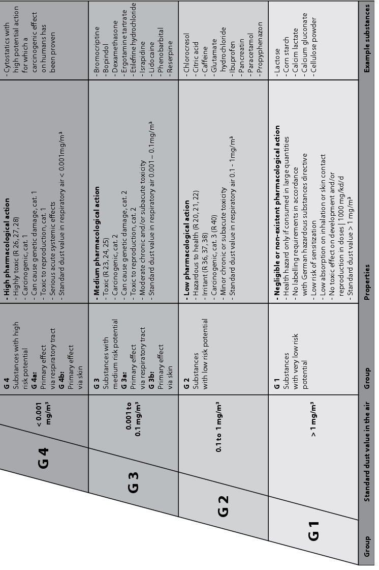
- Technical protective measures depending on the material group G1-G4 according to the German Chemical Industry Association (BG Chemie /1/) (figure 3)
- TRGS 900: German technical guidelines for hazardous materials (new Ordinance on Hazardous Substances), available under. In the Ordinance on Hazardous Substances (German Gefahrstoffverordnung, valid from 31.12.2004), closed systems are also required for CMR substances (carcinogenic, mutagenic and toxic to reproduction substances).
Figure 3 Technical protective measures depending on material group G1-G4 according to the German Chemical Industry Association
4 Measurement of the residue limits (OEL)
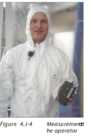
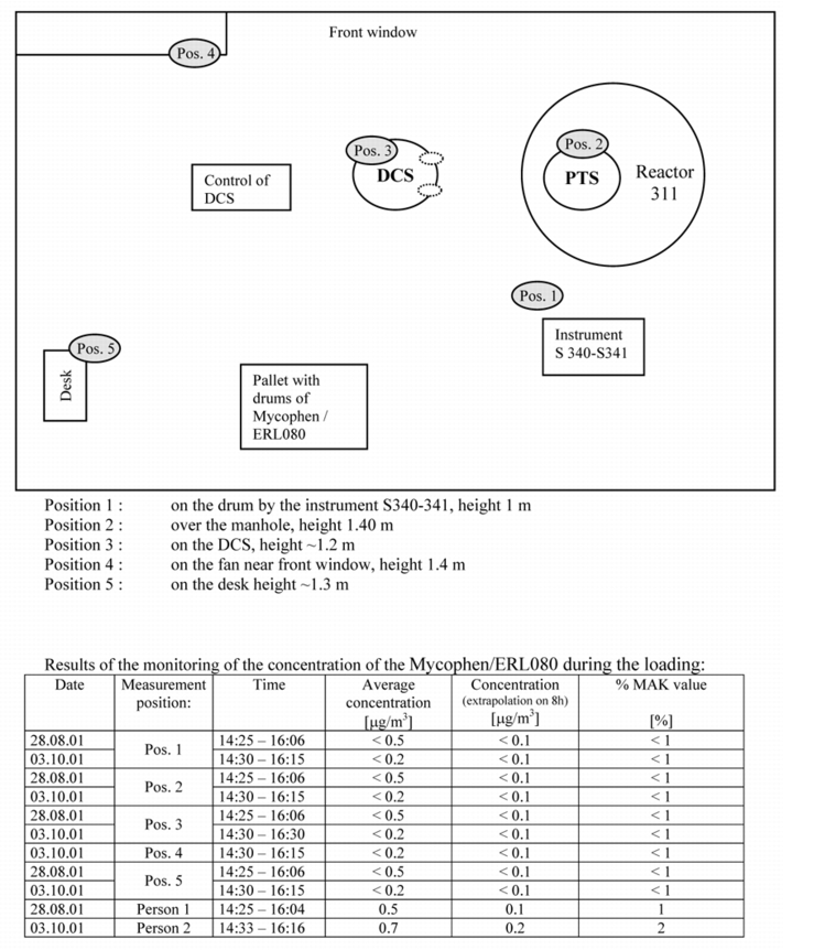
The OEL value is measured over eight hours, which corresponds to one working day. The average value must not exceed the required value during the measuring period. This value is measured with special measuring instruments (e.g. laser spectroscopy by the company rapID) or with filter systems which are then analytically evaluated in certified laboratories. It must be ensured that measurements are taken at the critical points, such as when docking on to and off from the containment system. Measuring instruments and filter systems should be installed close to the operator's respiratory tract (see figure 4) and at critical points in the room, for example at personnel and product locks.
 For a supplier of containment systems, it is difficult to guarantee a required value, as this can be influenced by several different factors.
In particular the frequency of changing the container should be mentioned here. If only one drum is filled during a shift, the average value can be much lower than if 20 drums are filled every hour. Other factors for achieving a very high level of containment are the particle size, air exchange, and air pressure.
With the measurements, you should also aim to carry out intermediate evaluations and not only consider the overall result across the day. These intermediate values are indispensable for recognising peaks in critical working steps. With each OEL grade, limits should be defined for the peaks, which must not be exceeded (figure 5).
 |
All systems are subject to wear and tear, which is why regular monitoring is important. It is advisable to perform a measurement in accordance with SMEPAC (Standardised Measurement of Equipment Particulate Containment). The SMEPAC recommendation was compiled by a working group involving representatives from the industry, engineering and consulting firms, and suppliers. The ISPE (International Standards for Pharmaceutical Engineers) has published the Good Practice Guide Assessing The Particulate Containment Performance Of Pharmaceutical Equipment, which is available from the ISPE website (www.ispe.org). This Good Practice Guide is intended to enable unification of the measurement procedures so that containment systems can be compared more easily.
5 Example of containment facility planning
Before planning a containment system in an API or pharmaceutical facility, the residue limits of the required level of containment should be defined (see figure 2). The OEL value (Occupational Exposure Level) defined ultimately determines the selection of the containment system.
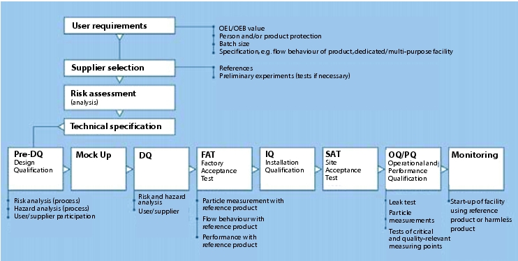
In the following example, an OEL of less than 740 nanograms/m3 TWA (Time Waiting Average) is required. In order to ensure compliance with this value, a DEL (Design Exposure Level) of 370 nanograms/m3 TWA has been defined. The DEL is the value that the containment system must meet, and is usually a certain defined percentage below the OEL value. Determination of the DEL value varies depending on the pharmaceutical or API manufacturer. In this example, the required OEL value has been divided by two in order to guarantee compliance with the required OEL value. Since this example deals with a system for discharging and filling highly-active APIs from containers such as Big Bags, and a comparable installation with this high level of containment did not yet exist anywhere in the world, an increased degree of qualification was required in the design phase. For this reason, a pre-DQ was carried out, which also incorporated safety aspects into the design with regard to personnel safety during the risk assessment. A feasibility study (mock up) was also executed during the pre-DQ, to assess whether the design of the facility is suitable for the requirements. An OEL measurement should be performed during the FAT (Factory Acceptance Test), to ensure that the technology in the facility complies with user requirements (user requirements, figure 6).
 |
A measurement reference and a suitable reference product for measuring the containment should also be selected. In this example, the ISPE baseline Assessing The Particulate Containment Performance Of Pharmaceutical Equipment was determined.Lactose was used as a reference product in accordance with the ISPE baseline.
Further requirements of the containment system were:
- Flexibility in size
- Easy to empty
- (also if the products to be manufactured have poor flow properties)
- Disposable containment system
- (i.e. no time-consuming cleaning validation of containers)
- Maximum container filling quantity of 350 kg
In particular, the disposable container and its design should have the following characteristics:
- Suitable for products with different flow properties
- The geometry of the container should allow self-discharging or emptying using suitable discharging aids
- Approved for use with hazardous materials, in order to enable transport of the products outside the building without outer packaging
- Approved for the following modes of transport: ship, HGV and rail
The costs of the disposable packaging system also played an important role, since a large number of containers is to be filled and emptied each year.
5.1 The FIBC (Flexible Intermediate Bulk Container)
as a containment system
A suitable containment system should be selected with regard to fulfilment of the requirements based on a risk assessment. In this example, the FIBC (e.g. Big Bag) is the suitable packaging medium.
 |
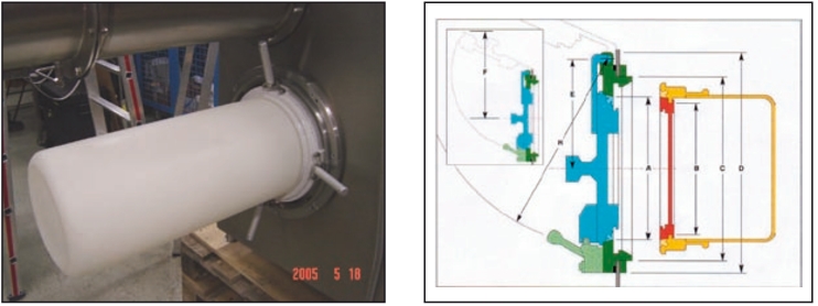
When connecting the FIBC inlet or outlet, in addition to the desired containment value, the product to be processed, and in particular its flow properties should also be taken into account. This determines the required connection diameter. Here a connection using an isolator was selected, since this was able to achieve the required containment of less than 370 nanograms/m3 with a connection diameter of 250 mm.
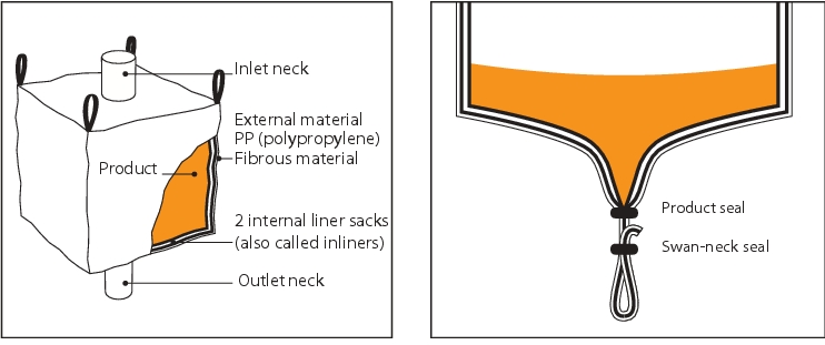
In order to achieve this high level of containment, the FIBC must be equipped with two inner film bags (inliners) at the inlet neck and the outlet neck. The internal inliner is filled with the product, and the outer inliner is required for double protection and for connection to the isolator. Both inliners are protected by the external shell of the FIBC during transport (figure 7).
5.2 Isolators as a containment system
To ensure that containment is maintained at a constant level, the isolator is operated at a constant negative pressure (-50 to -70 Pascal) and with 20x air exchange. The negative pressure is controlled by a frequency converter on the vacuum system, which increases the capacity if a leak is detected in the isolator, so that no particles are allowed to escape, even in the case of a fault (figure 8).
 |
During the risk assessment, each individual work step was precisely defined and its implementation recorded in the requirements specification for the design (figure 9).
|
Work step |
Requirement |
Implementation |
|---|---|---|
|
Connection of the external inliner to the isolator |
Adapt the outlet neck of the inliner to the (still closed) isolator |
Connection system that guarantees a dust-tight stable connection, with easy and fault-free operation |
|
Check outlet neck for tightness |
Leak test is required before isolators can be opened for attaching the internal inliner (with product) via the RTP (Rapid Transport Port). |
Leak test system in the connection system for the external inliner, which is verified and released by the control. |
|
Attach the internal inliner with product to the isolator |
Open the RTP. The negative pressure in the isolator means that the inliner with product is pulled into the isolator. |
|
|
Connect the internal inliner |
Prevention of any dust formation/open product handling |
Additional connection system in the isolator to enable safe and closed connection of the inliner. |
|
5.3 Transport and docking system for the FIBC
Because the FIBC is a flexible packaging material, it is recommended to always transport this in a frame. The frame has the advantage that the FIBC is fixed in the frame and can also be transported by pallet lifting trucks. The frame is also required for transporting the FIBC into the filling or discharging position using a lifting column.
The lifting column fixes and centres the transport frame of the FIBC. As an additional element, the lifting column includes a discharge unit for the product in the FIBC. The height of the discharge unit can be adjusted, so that once the FIBC frame is attached, this can be moved to the FIBC outlet to contact the cone on the FIBC. This stimulates the product flow. The lifting, lowering and rotation of the FIBC frame by the lifting column has been equipped with special safety features to protect the user and the Big Bag during the lifting and transport movements.
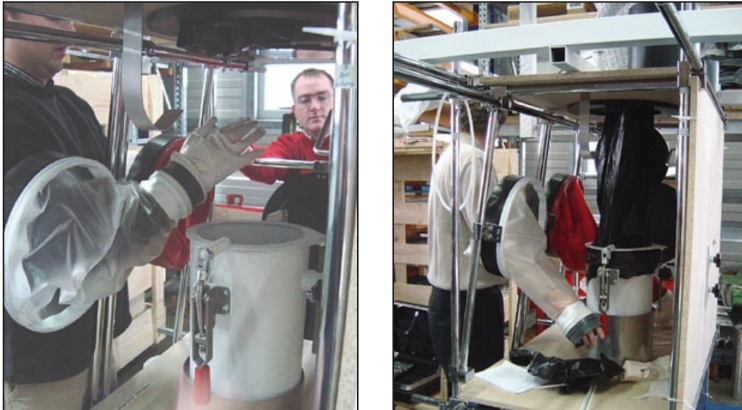
5.4 Feasibility study (mock-up )
Before the completion of the design and release for manufacturing, all components are constructed for the mock-up using dummies (e.g. adjustable frame with gloves to represent the isolator). This enables the operator to test the individual steps. This has the advantage that the operator feels integrated in the decision process, which leads to acceptance of the new system. The cleaning procedures and the exclusion of components for cleaning can also be tested in this way. The mock-up is part of the mechanical pre-DQ (figure 11).
 |
5.5 Particle measurement of facilities in accordance with SMEPAC
Due to the new technology, during the Factory Acceptance Test (FAT), a particle measurement should also be carried out on the facility components. For this measurement, a concept is developed that includes the core points of the ISPE baseline (replacement material lactose for measurement, air exchange, alignment of filter system IOMs, closed housing around the containment system). First, the facility components were structured at the customer site in accordance with the planned installation. To enable this, all the facility technology was constructed in a frame, in order to adjust the range of measurements to suit the final facility installation at the customer site. The inside of the frame was covered with film. All cable ducts for controlling the components were tightly closed (figure 12).
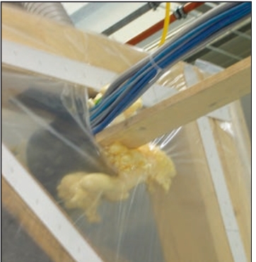 |
Figure 12 Wooden frame construction |
 |
One area was designated for entry of personnel through the lock into the contained room. Lactose was used as a surrogate product. To avoid contamination during entry of personnel through the lock, a lactose-free zone was also set up outside the measuring area. A sign bearing the information "Lactose-free zone - Access for authorised personnel only" was attached to the doors to the relevant area. The lactose transport via a vacuum conveying system from the discharge container (big bag) outside the hall into the area was also hermetically segregated. The lactose was transported into a bin above the contained room via a pneumatic conveying system. The bin was designed to simulate the dryer that empties its contents into the FIBC during the measurement. At the same time, the room in which the measurement was to take place was flushed with purified air by HEPA filters (three air exchanges per hour). The system components were cleaned with purified water, because wipe tests were performed as well as the particle measurements (see figure 13).
The IOM sampler was attached in a similar way to the SMEPAC. In the SMEPAC, the position is defined precisely on or, if applicable, above the interface. The samplers were installed under the docking station while the FIBC was filled. This meant that in the event of dust escaping, the particles, which are guided downwards by the air flow, would be collected in the filter. Two samplers were therefore positioned approx. 10 centimetres below the docking station and two more were positioned immediately adjacent to the docking station, in accordance with SMEPAC. The other samplers were attached according to SMEPAC at the glove ports on the isolator, on the filters, close to the operator's breathing area, and in the room. Persons who were present during the measurement had to put on uncontaminated protective clothing, gloves, and head coverings before entering the room.
The measurement was documented using video monitoring. This enabled individual work steps to be followed and suggestions for improvements to be defined, even after the tests. The video documentation also makes the subsequent compilation of the SOPs (Standard Operating Procedures) easier. Before start-up, the video recording can be used to explain and discuss each individual movement with the operating personnel.
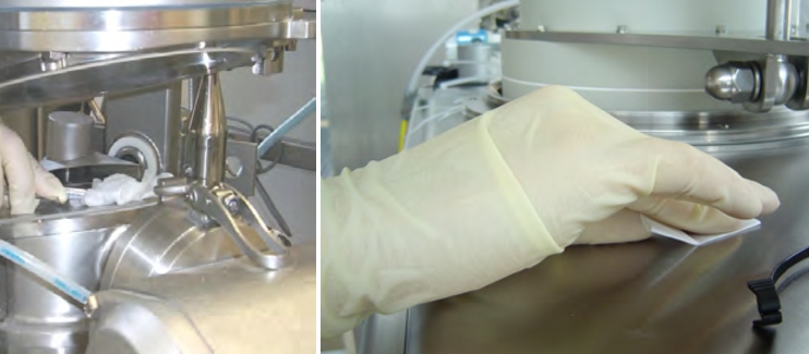
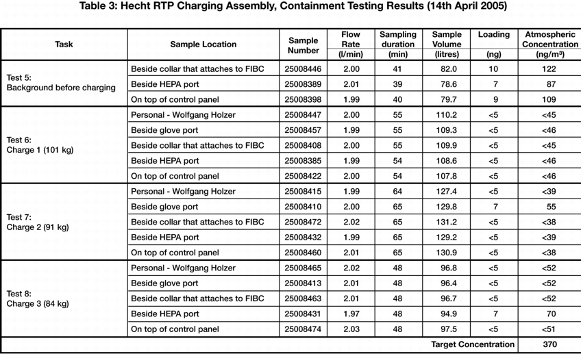
After the particle measurements (one background measurement to measure the basic load of lactose in the room, and three measurements with the products), wipe tests were performed on critical surfaces, in order to determine the level of surface contamination. Each discharging and filling process was repeated and recorded three times. The samples were evaluated in a laboratory in the USA recruited by the end customer, since there is currently no lab in Europe capable of evaluating concentrations in the low nanogram range.
The results fulfilled and confirmed expectations in all areas. The background measurement (how much lactose was present in the room before the measurement) and the measurement results of three consecutive measurements were recorded in the measurement log. A result of under 100 nanograms/m3 was achieved in nearly all cases.
5.6 Documentation and results
The measurement was documented using video monitoring. This enabled individual work steps to be followed and suggestions for improvements to be defined, even after the tests. The video documentation also makes the subsequent compilation of the SOPs (Standard Operating Procedures) easier. Before start-up, the video recording can be used to explain and discuss each individual movement with the operating personnel.
After the particle measurements (one background measurement and three measurements with the product), wipe tests were performed on critical surfaces to determine the level of surface contamination. Each discharging and filling process was repeated and recorded three times (see figure 14). The samples were evaluated in a laboratory in the USA recruited by the end customer, since there is currently no lab in Europe capable of evaluating concentrations in the low nanogram range.
 |
6 Containment weak points
to enlarge, click here!Not only the points in the process at which containers are emptied or filled should be graded as critical. All points at which leadthroughs from the closed process are applied from the inside to the outside must be taken into consideration. This includes, for example, shaft leadthroughs on stirrers, dosing systems and shut-off flaps, etc. Other weak points are the exhaust systems and filter facilities for filling or emptying solid materials. Here, it is necessary to use systems in which the dust collection pot and the filter medium can be disposed of when closed. For ex-protection reasons, it may be the case that facility components have to be inertised. Inertisation means excess pressure in the system. The excess pressure, even if it is in the mbar range, stresses flexible connections such as tri-clamp and flange connections. When testing the tightness, the possible maximum pressure value must also be tested in the case of pressure fluctuations.
to enlarge, click here!Note that Atex (Atmosphere Explosible Directive 94/9/EC - Use of facilities in an explosive environment) and containment can also contradict one another. Atex recommends inertisation for dust explosive products or if seals are used, which should themselves be electrically conductive, but FDA or food conformity is required for a particular reason. (Seals that are food conformant or FDA conformant are usually white and not conductive.) Containment as operator protection requires negative pressure inside equipment and containers.
Even when cleaning the facility, freedom from dust must be ensured. The best solution is CIP (Cleaning in Place) and DIP (Drying in Place). With this solution, the facility is not opened and contamination is not possible. For containers and simple equipment, this can also be easily installed and validated. For complex facility components such as a drum filling with buffer hopper, dosing system and other additional equipment, CIP is difficult to implement. Critical points often have to be cleaned manually afterwards. With manual cleaning, contamination must be prevented before opening the system. For this reason, a placebo product should be used the first few times the system is cleaned in order to validate and, if necessary, optimise the cleanability. The use of a placebo instead of the critical API ensures that no contamination occurs if the system has to be opened at critical points.
7 Containment systems for filling and emptying
drums
Suitable systems must be selected for this, according to the required OEL or OEB.
7.1 Drum filling with endless liner
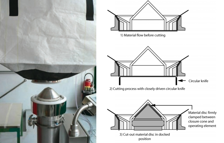
A primary containment system for filling drums is the endless liner system. This system includes a drum filler head which is designed to receive a liner cassette. This liner cassette can be made from hard cardboard, plastic or stainless steel. All cassettes are equipped with a certain quantity of liner. In most cases, this is approx. 30 to 50 m. A special feature is the mounting of the liner so that a closed system is ensured when the end of the liner is reached. It must also be possible to change the liner cassette without contamination. The already sealed liner end is pulled out to a sufficient length before filling the liner bag, and sealed to the liner bag with an expanded clamp. After filling, the liner can be separated using various systems. The liner inlet and the new liner floor must always be sealed automatically after separation.
The following systems are feasible:
- Welding of the liner: The weld should be at least 1 cm wide and automatically be separated in the middle so that there are no open points.
- Another variant is applying adhesive tape at the separating point. The separating point is cut in the centre with a pair of scissors. Both ends are then sealed with adhesive tape. With this version, containment of less than 1 mg/m3 can be achieved.
- Clipping with subsequent separation between the clips is less effective: There could be material in the space between the two clips. In any case, the ends should be sealed and local aspiration applied.
The advantage of endless liner systems is that no containment can take place outside the inliner, such as during filling in isolators.
7.2 Drum filling and emptying with DCS
(Drum Containment System)
Another primary containment system is a special adapter head for emptying and filling drums with inliners.
 |
Figure 17 Drum Containment System for drum filling, by Hecht |
 |
When filling a drum, the inliner is connected to the filler head using a special connection technique and the drum edge (with just one inliner) is pressed against a gasket on the bottom part. If filling with two inliners, the second inliner is again specifically connected to the filler head. With this version, primary containment of less than 1 mg/m3 can be achieved. With this system too, the inliners are sealed with an adhesive tape and separated in the middle after filling. The inliner is sealed onto the filler head with the gloves. The remaining liner on the filler head and the remaining liner on the outer filler head mean that the system is kept completely leak-tight after filling (figure 17).
Additional equipment: Locks for bringing parts into the filling head (e.g. sampling), exhaust filter with push-through filters (contamination-free filter change), for inertising and rinsing the filler head before filling, cleaning drum for Cleaning in Place of the filling or emptying head (figure 18).
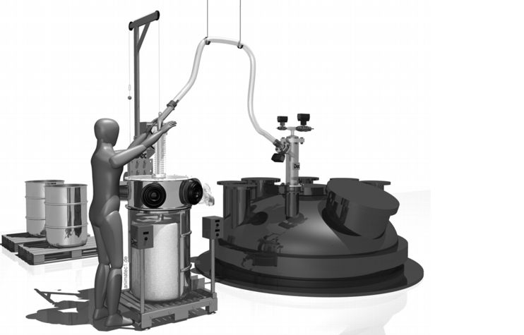
An almost identical system with similar function is also used for emptying drums. In this case, however, a suction lance is required, which sucks the product out of the barrel. With a Powder Transfer System (PTS), the product can, for example, be safely and inertly emptied into a reactor (figure 19).
 |
Especially when filling reactors, a material lock should be used as product transfer in accordance with Atex. Direct coupling of an unpressurised container or pack to a pressurised container should be avoided. It is advisable to use a Powder Transfer System (PTS) to fulfil this function. With the PTS system, a product quantity from the container to be emptied is sucked into a lock with a vacuum. The lock outlet to the reactor is secured. The lock inlet is sealed after filling the PTS body and kept under vacuum until the lock does not contain any more oxygen. The lock is then inertised with nitrogen and the product is discharged into the reactor by opening the outlet flap. The PTS is designed with the same pressure as the reactor (3 bar or 6 bar).
With the combination of the Drum Containment System (DCS) and the associated Powder Transfer System (PTS), toxic, highly potent and sensitive products can be emptied safely. An important advantage is that the operator can view the product via a borosilicate disc, despite the closed system. With the gloves and suction lance, it is possible to empty even lumped products or products that do not flow easily. The suction lance is also available in combination with an integrated lump breaker. Access to the product via the glove on the DCS system offers a significant advantage besides other closed systems.
Cleaning in Place is possible during both filling and emptying.
7.3 Big Bag emptying and filling with a protective liner system
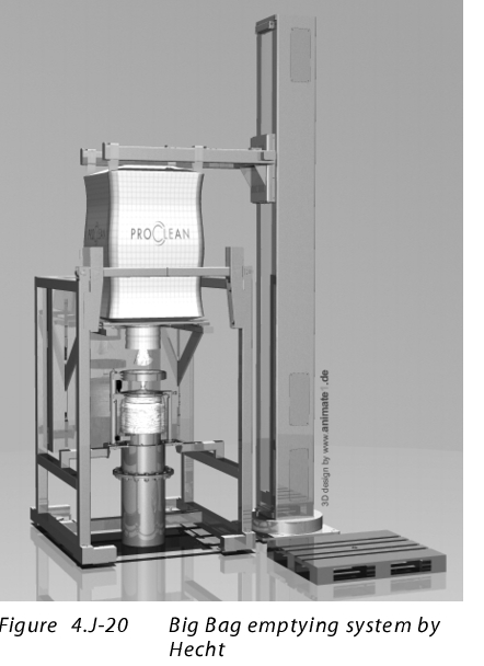 to enlarge, click here!This system is also a primary protection system for emptying and filling Big Bags (figure 20).
Emptying of Big Bags via closed double ring systems has already prevailed in the industry. The only disadvantage is that before connecting and after emptying, the Big Bag outlet neck is open. This weak point was solved by a protective liner connection system. With this, the Big Bag inlet is connected to a protective liner before it is opened. At the same time, the protective liner seals the system connection so that no contamination can occur here. Both inliners (1x inliner in the Big Bag, 1x inliner protective liner system) are connected to each other via a hardboard ring and clamped together so that they are dust-tight. The hardboard ring is removed after emptying and disposed of with the empty Big Bag. If the Big Bag is emptied, the inliners above and below the hardboard ring are sealed. The seals below the hardboard ring are separated in the middle. The Big Bag outlet and the inlet into the filling system remain sealed.
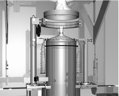 |
Figure 21 Protective liner emptying system by Hecht |
The same system with a similar procedure is also used to fill Big Bags. With this system, OEL values between 1-10 μg/mі can be achieved. With additional equipment, this can even be less than 1 μg/m3 (figure 21).
The Big Bag has advantages over other systems in terms of storage, the possibility of emptying, and production costs. The Big Bag also does not have to be cleaned after emptying if it is used as single-use packaging. A further advantage of the protective liner system is the ability to empty and fill different types of container without changing the system. The protective liner system can be used, for example, to fill and empty Big Bags, containers, Mini Bags (Mini Bag systems instead of drums) and small bags. Cleaning in Place is possible during both filling and emptying.
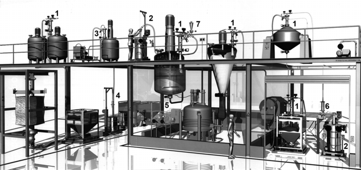
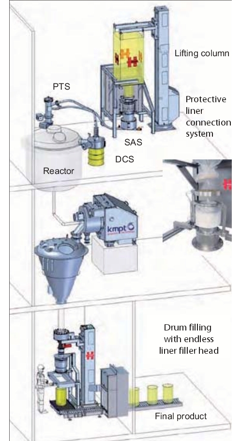 |
Figure 22 Total containment system in API production |
8 Container systems
Containers are classic systems for internal transport and for storage of intermediate products and final products. Container systems have been used successfully in the containment area for a long time. A distinction is made between the following container systems (figure 23).
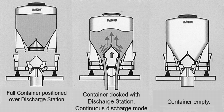 |
8.1 Container with outlet cone for discharging
Execution: In the container outlet, there is a closure cone which is paired with a flexible counter-cone at the discharging station. The container is emptied by lifting the cone.
The cone not only performs the function of discharging the product and the function of a containment system. Through an automatic lifting adjustment of the cone to different positions, a predetermined volume can be emptied from the container. The cone can be used as a dosing system. The emptying station is then either set on weighing cells (withdrawal weighing) or the next process is weighed (gain in weight). The different height adjustments of the cone also make it easier to empty for different materials. Partial emptying of the container is possible.
A further advantage is that the large discharge cross-section also makes it possible to discharge products that do not flow easily. The sealed cone system is also available for emptying Big Bags. The advantage of this system is that the Big Bag is used as a single-use system. This means that time-consuming cleaning of the container is not required. The purchase price is more favourable compared to a similar container-based system. A further advantage is the better suitability of a flexible container rather than a stiff container for products that do not flow easily (see figure 24).
 |
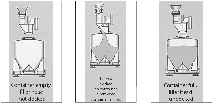
8.2 Containment Transfer Unit at the container inlet for filling
Execution: A special containment lid is attached to the container inlet. When closed, the lid is securely positioned over the filler head and removed from the container inlet. The container lid is so neatly fixed through the incorporation in the filler head, that the filler head and container lid are largely free from product accumulations after the system has been filled. The filler head is located above the container filling station and is docked to the container inlet via a lifting device (figure 25).
 |
 |
Containment in mechanical systems such as the cone system or the Containment Transfer Unit greatly depends on accuracy during manufacturing and maintenance. In this system, visible freedom from dust is only possible to a limited extent.
A safe system for filling a container is the cone system. As described under cone discharge, this system is also suitable for filling flexible containers such as Big Bags. Examples for the use of a cone discharge and filling system in formulation/packaging are shown in figure 26.
8.3 Split valve systems
Execution: A shut-off flap is virtually separated in the middle. The two separations are now applied to the systems separately. One system is called the active flap and is equipped with the drives. It is attached to the discharging or filling position. The passive part is found on the container inlet and outlet. During filling and discharging, the two parts are connected as with the cone system, and are then opened. The discharge opening in this system, however, is designed for "small" cross-sections and is only of limited suitability for emptying products that do not flow easily without additional discharge aids.
 |
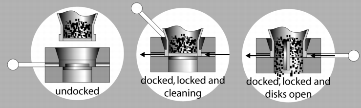 |
With a standard version, containment of between 10-100 mg/mі is achieved. In order to achieve containment of 1-10 mg/m3, a special version is required in which the space between the flap halves is rinsed and dried before docking. Here, it must be ensured that the flap seals are always in perfect condition, so that no liquid can enter the product space and then cause the product to bake off during the next filling process. This system, like the cone system, should only be considered a closed system if it is maintained regularly and the seals replaced.
Cleaning in Place is possible for container systems to a limited extent. The level of automation is also a plus point in the use of containers. Container systems can be transported completely via AGVs (Automatic Guided Vehicles) and automatically emptied, filled and cleaned.
8.4 Laminar flow, Glove box systems (isolators)
Laminar flow systems are used for protection of the product, person and room. The working area of the laminar flow system is supplied with clean air from above through H14 filters. Aspiration takes place opposite the user position or the working area through high-performance HEPA filters. These systems are particularly suitable, for example, for separating the manual weigh-in area for small quantities. Other possible uses are the emptying of sacks, drums, Big Bags and containers, if these do not already have a primary containment system or cannot be emptied by a containment system. The dust load inside a laminar flow system can usually be improved a thousand-fold compared with the exterior. An exact specification of the OEL value to be achieved cannot be guaranteed.Laminar flow systems only reduce the risk of cross-contamination to a certain extent. Comprehensive cleaning when changing between different products and contamination-free clothing of the operators must be ensured.
Glove box systems and isolators are mainly used for personnel safety. Compared with the laminar flow systems, in which the operator intervenes in the system via an air curtain or, in bigger systems, even finds himself inside the laminar flow, this is not possible with a glove box or isolator system. If manual intervention or a manual operation is necessary within the system, this is either executed via a manipulator within the system or by the operator wearing gloves.
Glove box systems and isolators are used for hazardous and highly potent materials. As these systems are also used for secondary containment, the inner area of the glove box or the isolator is contaminated. It is therefore important to ensure that contaminated parts are first isolated, particularly when discharging parts from inside. An OEL value of less than 1 mg/m3 can be achieved here.
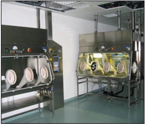 |
Figure 29 Glove box system |
9 Filter systems
Filter systems are often forgotten in the consideration of containment systems. But especially here, the system must meet the same requirements as the entire production process. This means contamination-free changing of the filter medium and of the dust collection pot. Washing and subsequent cleaning must be carried out before inserting the new filter.
Recommended additional equipment is a monitoring system on the clean gas side, in order to prevent carry over or cross-contamination (figure 30).
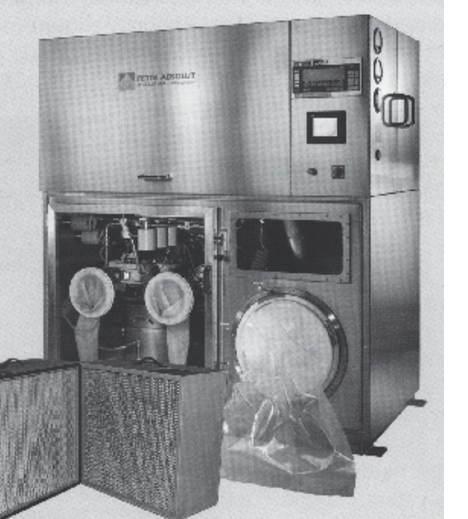 |
Figure 30 Filter system |
10 Sampling
Samples must be taken for in-process controls and for the release of manufactured products. Sampling must be representative of the manufacturing batch. The installation location of the sampling system must be precisely selected, especially for hazardous and highly-active substances. With the sampling system, a defined volume is taken from a closed system over a period of time and filled into a container. The container must then be closed, removed, and transported to the (analytical) laboratory for analysis. It must also be possible to open the container for subsequent analysis.The sampling system must be completely closed to the outside. Here are two examples of suitable systems:
10.1 System 1: Sampling via a withdrawal screw fitted in the production area
The screw can be fitted in a downpipe or buffer container. The worm screw continuously withdraws a representative sample across the entire cross-section. The sample is filled into a container. This container is connected to the sampling system via a split valve system. The split valve must be closed for withdrawal of the sample container. The half of the valve with the sample container is uncoupled and removed by the operator (figure 31).
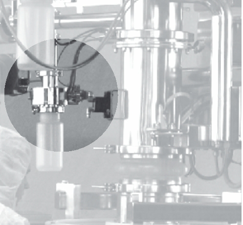 |
Figure 31 Screw sampling by Hecht |
Advantages of this system:
- Withdrawal of a representative sample
- Simple integration into an existing facility
Disadvantage:
- Only WIP (Washing in Place) is possible. The system must then be opened and cleaned manually.
10.2 System 2: Sampling via a micro Powder Transfer System (MPTS)
This system withdraws the product using a suction lance integrated in the process. The suction lance can be installed statically or dynamically. The product is sucked into a bottle located in the glove box by vacuum. With this system, samples can be taken from different positions. It must only be guaranteed that there is a product collection that can be aspirated.
The sampling container can be installed at a position far from the process.
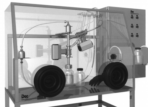 |
Figure 32 Micro |
Advantages of this system:
- Withdraws a representative sample.
- Can be easily integrated in an existing facility.
- WIP (Washing in Place) is possible.
11 Containment on equipment
Two further examples show that containment must also be ensured within processing steps.
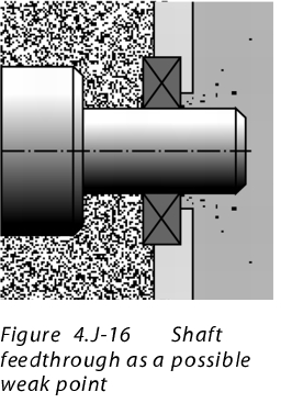
11.1 Example 1: Shaft leadthroughs
to enlarge, click here!This area must be considered as particularly critical. In a closed system, there is penetration from the inside to the outside. The shaft leadthrough is usually fitted with special seals and air or nitrogen rinsing. In particular for containers that are pressurised with excess pressure, a leak test is particularly important. In consideration of containment, these points should be measured separately, for even the smallest leaks that cannot be detected by a monitoring system cause the OEL4 or OEL5 value to be exceeded. The stored air rinsing should also be purified when changing the product.
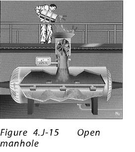
11.2 Example 2: Filling and discharging cone dryers
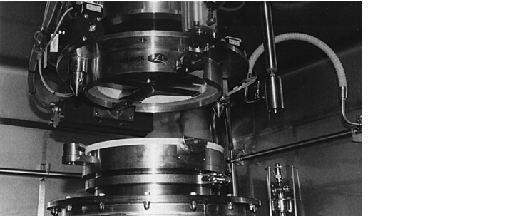
Usually, process equipment is permanently closed together. Cone dryers are an exception. Here, the inlet and outlet must be uncoupled. This should be executed with split valves, as described above for containers (see chapter 8 Container systems), as with this system, the active flap can be docked on the cone dryer inlet and outlet via a lifting device.
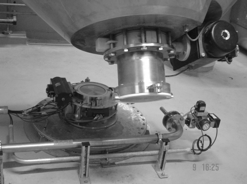 |
Figure 34 Cone dryer |
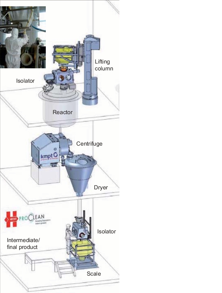
11.3 Practical example of a containment API plant
 |
|
Summary: There are now a number of possibilities for achieving primary and secondary containment. For each type of use, the optimal variant should be selected in terms of:
In any case, risk analysis should be carried out before selecting a containment system and during the DQ (design qualification). The system should be qualified. Cleaning of the containment system should also be validated. Regular revalidation is recommended at shorter intervals straight after the PQ (performance qualification), in order to obtain information on the safety of the system. |
