Testing for tightness and particles
Here you will find answers to the following questions:
|
12.I.1 Testing for tightness
To prevent microorganisms and external atmospheric oxygen from penetrating filled immediate containers such as ampoules and bottles, these must not have any cracks or fissures. The containers are examined for these faults by a visual optical control, and faulty containers are rejected. Since this method cannot guarantee a 100% certainty, various methods are used to test the containers for tightness.
Depending on the product, the size of the container and the visual or automatic electronic inspection, different methods have become established.
- Dye bath (usually blue) for ampoules and bottles (old procedure, used for small batches or for solutions with low conductivity)
- Water bath for freeze-dried drug products
- Steam overlay for oily solutions in ampoules and bottles
- Crack test in a high-frequency range for electric current (for solutions with a conductivity >5 mS/cm)
- Weight difference compared to an average calculated from samples
The test for tightness should ideally be performed as the final step in the operational cycle before the containers are sorted into transport packaging, since all steps up to this point are associated with a risk of cracks and fissures.
For tests that involve a dye bath, water bath or steam overlay, this is obviously not possible. The high-frequency crack test for electric current has therefore become very popular. Regardless of which method is used to detect a leak, it is important to investigate whether the cause is systematic or a one-off event. The appropriate measures to prevent cracks in glass objects or leaks in plastic objects must be complied with (see figure 12.I-1).
| Measures for the prevention of cracks |
|---|
|
12.I.1.1 Testing for tightness using a dye bath
Following steam sterilisation in the chamber autoclave, the dye bath test is carried out in the chamber (if technically possible) or in a separate, conventional, modified pressure vessel in upright magazines.
The containers are immersed in the dye bath and subjected to negative pressure. If the container contains a crack air escapes and, following overlay with positive pressure, the dye solution passes through the crack into the container. The dyed contents can be recognised by visual control and the container rejected.
For small numbers of containers, the dye bath is a relatively cheap method and does not require too much technical apparatus. In contrast, the method has the disadvantages listed in figure 12.I-2.
| Disadvantages of the dye bath test |
|---|
|
12.I.1.2 Testing for tightness in the water bath
(for freeze-dried drug products)
Similar to the dye bath test, the water bath test is performed in a modified pressurised container. Purified water is used.
| Testing in the water bath |
|
|---|---|
Advantages:
|
Disadvantages:
|
12.I.1.3 Testing for tightness in steam
Containers that are filled with oily solutions are subjected to evacuation and subsequent vapour phase in the autoclave, so that steam can penetrate into the container. This results in a visible turbidity of the oil phase, or in the case of larger cracks, a visible oil/water phase in the bottom of the container. Both can be detected visually and electronically.
12.I.1.4 High-frequency crack test
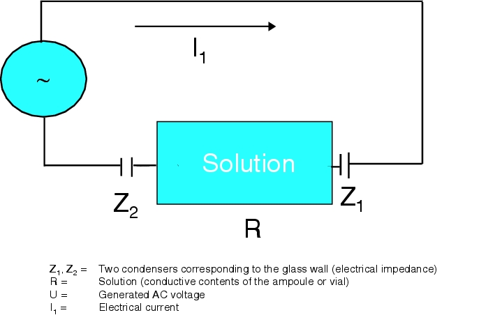
The measuring principle is based on measuring current flow when a high-frequency high voltage (500 Hz, 16-30 kV) is applied to the glass container (ampoules, vials). The current flow measured for an intact container is used as a control variable (baseline) for the container. A constant low electrical discharge between the electrodes and the test object can be detected.
Figure 12.I-4 shows the test set-up. According to Ohm's law, the current I flows as follows: I1 = U / Z1 + R + Z2
In a leaky container, one of the electrical impedances is decreased, which leads to a higher current flow (up to a lightning surge) and considerably exceeds the baseline signal.
The difference of current flow between the baseline signal and a higher current flow is represented on diodes, and is used as a criterion for detection in accordance with Ohm's law I = U/R + Z. Under constant current, a higher current flows for a defective container.
|
The principles described above mean that insufficiently conductive liquids (for example, WFI) are not suitable for this test. One possible workaround is to enrich the cooling water in the autoclave or the immersion bath with an electrolyte (for example, NaCl), since then the contents of the container become conductive in the case of leakage.
Sensitivity of the method
The principle of the test also means that each drug product and each test point, such as floor to middle, and middle to the tip or neck of the container, has to be assigned a specific setting for sensitivity and high voltage (see figure 12.I-5).
|
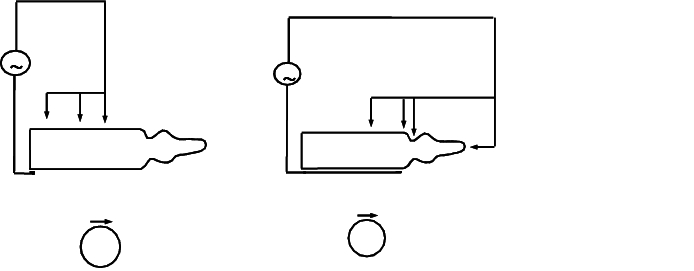
Over many years of experience and cooperation with pharmaceutical companies, machine manufacturers have developed electrode position configurations/high voltage values and sensitivity settings for 1-100 ml glass containers. This takes into account the solution properties such as conductivity, container surface moisture, and technical properties of the container. Rotation of the containers during the process under the electrodes is standard practice for identifying any cracks that may be in geometrically inaccessible positions.
Test objects for function tests
Testing the functional reliability of a crack test machine would require containers with cracks of a defined size. Since it is not possible to manufacture containers with cracks of a defined size, this was attempted using ampoule models made of Teflon with inbuilt resistors. This method has proved largely impractical, since the min/max settings of the test parameters necessarily cause electrical arcs, which very quickly destroy the test object. It has therefore become common practice to use containers as test objects (for testing functional reliability before the start of production), which have been identified as faulty in previous production processes. Containers with cracks that have been technically induced in the lab (by shocking the hot ampoule tip with water and hence forming micro-cracks) and have been microscopically evaluated can also be used.
All test objects only have limited suitability:
- Run off and drying of the solution on the crack causes the crack to close.
- Cracks are enlarged by electrical arcs.
- Thin glass areas (tips of balloons on ampoules or point-cut countersinks) may shatter.
This means that a constant supply of containers with faults must be available for use in functional testing.
Assessment of the method
When testing containers using solutions with a conductivity of considerably more than 5 mS/cm, a reproducibility of >96 % is expected. The method also enables you to simultaneously identify containers with thin glass areas that are later in danger of breakage during transport.
12.I.1.5 Testing for tightness by weighing
Weighing a large number of visually inspected containers and calculating an average enables the individual weight of a container to be compared and a calculated plus-minus weight difference can be used to determine whether there is a significant increase or decrease in total weight. This would detect any leakage in the container. A more exact inspection of the container is absolutely necessary. This procedure is only practical in transport or packaging facilities in which weighing equipment can be integrated into the system.
12.I.2 Particle test
Particle contamination refers to foreign, mobile, undissolved particles that are unintentionally present in the solution, with the exception of gas bubbles (Pharm Eur.). The test can either be performed visually, using a semi-automated procedure, or by a validated electronic procedure that would be regularly controlled.
Annex 1 of the EU-GMP-Guideline, point 90, requires that: "Filled containers of parenteral products should be inspected individually for extraneous contamination or other defects. When inspection is done visually, it should be under suitable and controlled conditions of illumination and background".
The European pharmacopoeia, section 2.9.20 Particle contamination - visible particles (fig. 2.9.20-1), describes that a vertical mat black plate of a suitable size should be aligned next to a suitably sized vertical non-reflective white plate. A source of white light should be used that generates 2,000 and 3,750 Lux. After the content of the container has been lightly whirled, the container should be turned so that no air bubbles remain in the liquid. The liquid is then inspected for 5 seconds in front of the white plate. The inspection is repeated in front of the black plate. Any presence of particles is recorded.
To satisfy the requirement for inspection for "other" defects, the use of magnifying glasses (1.5x) considerably improves the detection of cracks, external impairments and damage to seals or tips (of ampoules). This also applies for the inspection of the external shape of the container, such as length, diameter, colour, defective material (inclusions in the glass, misshapes from glass forming at the manufacturer). This also enables particles to be detected more easily.
In order to be able to detect particles in a solution, the particle must visibly stand out from the solution, or at least, the interface between the solution and the particle must be visible under light. This requires an adequate light source and a coloured background on the object to be inspected. It must be possible to comply with the normal viewing distance of approx. 25 cm.
Particles and defects are identified by:
- Different colours
- Different transparency
- Solid shapes
- Varying density and hence light reflection at the interfaces
- Varying density and hence light penetration
- Cosmetic, external faults on the container.
This results in different options for visually and electronically recognising particles.
12.I.2.1 Visual inspection
An important task of visual inspection is to identify the type and material of the particle from its visual impression, and to identify the cause and place of contamination (see figure 12.I-6).
| Type and material of the particle |
Cause and place of contamination |
|---|---|
Metal, ceramic, glass |
Pump abrasion |
Rubber particles |
Seals of filter housing |
Fibres, particles from environment and improper handling |
Filter assembly |
Adhesive particles of stopper material and fibres from the environment |
Rubber stoppers |
Semi-melted fibres and particles and glass chips from glass manufacturer |
Containers |
Particles from conveyors for stoppers and sealing components |
Filling machine |
Glass splinters |
From damage and breakage on the filling machine |
Sintered or cracked ingredients of the solution, crystallisation |
Sealing processing step |
A visual assessment and classification of the particle is not always sufficient, in which case an analysis of the isolated particle must be carried out. It has been shown that with sufficient experience and exact knowledge of the production steps, the particles can be classified and assigned by the visual identification alone. Material inspection is only required in rare cases. In general, staff require extensive training before they are able to identify particles, if these reach a size of approx. 80 mm. It is important to take into account any magnification caused by the shape and diameter of the container. During the training program, the control employee should be introduced to all recognised types of fault.
| Frequency of particles in solutions |
|||
|---|---|---|---|
Ampoules |
Glass bottles |
Plastic containers (clear) |
|
High Low |
|
|
|

In all containers, the dosage (fill level) and the presence of cracks should also be checked at the same time, and any conspicuousness evaluated as a type of fault.
The visual inspection is reliant on staff management, expectations, clear instructions and controlled handling:
- Handle container with as little movement as possible - avoid shaking
- Do not begin to turn the object in the hand until the start of the observation in the visual field - any "small particles" deposited on the floor of the container (in some cases below the visibility level) should be detected.
- Stick to the observation system from bottom to top of the container.
Good training and constant visual inspection activity should lead to an "automated" (almost subconscious) ability of the member of staff to reject faulty objects. The member of staff should be made aware of their responsibility by emphasising the importance of the visual inspection as the last possibility for detecting faults. This motivation is particularly important if fewer faulty objects occur and a sense of doubt ("there are no faults here anyway. ...") leads to negligence. A failure rate of <0.5% should be aimed for as a good production result.
Visual optical controls are based on the laws of probability. If a presence (detection) or absence (non-detection) is possible, this is a chance result. The frequency of an event (e.g. detection), for example "70x detected in 100 observations", is expressed as a fraction 70/100 = 0.7. This is described as the relative frequency of the event. With a sufficient number of observations, the relative frequency can be expressed as a numerical value for the probability (P, statistical probability).
12.I.2.2 Visual control with semi-automated equipment
Bottles
These are control machines in which the containers are fed individually via a conveyor belt. The container is held in mechanical supports, and in front of the observer, is turned upside down and rotated around its own axis at least once. The characteristics of a particle can be observed (reflection, flotation, falling speed, colour, etc.).
Within the required 5 seconds observation time, the solution contents are checked for particles and the external integrity of the container is checked. Objects classified as good are subsequently subjected to tightness weighing or a high-frequency crack test.
Ampoules/vials
The ampoules/vials are loaded from their delivery containers into a loading receptacle (with glass bottom) of the machine. The objects undergo a preliminary inspection from underneath through the glass bottom. The ampoules are checked to ensure that the lance part is the correct shape and that no impurities have resulted from the tip sealing process. Vials are checked to ensure that the crimping cap is the correct shape and that the cap is the correct colour.
The machine mechanics automatically load the containers (4 to 6 at a time) into a rotation mechanism and turn them. When the rotation stops, the control employee inspects the containers. The solution in the container continues to rotate and any particles that are also rotating can be identified. Defective containers can be rejected at the touch of a button.
For containers containing powders or lyophilisates, the rotation speed must be regulated (1-2 x per observation time) so that faults (such as black particles, glass splinters) are not "washed away", but instead are made clear.
12.I.2.3 Electronic control for visible particles
There are three main electronic control procedures in use that have been developed by different machine manufacturers:
- Rotation of the container and measurement of the shadow of moving particles using illumination once they have stopped moving.
- Rotation of the container and measurement of the reflection of light scattering by cameras, once the particles have stopped moving.
- Camera systems for image comparison against an imported ideal image of the container.
In principle, all electronic procedures perform a 2-station and/or multiple control (measurement).
The advantage of all three procedures is the elimination of human error such as:
- Decreasing visual acuity
- Decreasing stamina
- Temporary alertness
- Physical and psychological changes throughout the day
- General daily form throughout the week
and a possible higher inspection ability and sensitivity settings for different particle sizes.
The disadvantages are:
- High purchase price
- Complex validation activities and specific long-term technical support
- Relatively high mistaken evaluation as poor due to misinterpretation of physical states that are thought to be particles
- Impossibility of detecting certain faults that are outside the detection spectrum (preliminary inspection of tips or subsequent control necessary)
In addition, none of the three systems is capable of interpreting faults. These must always be classified by personnel after the control.
| Electronic control for visible particles |
|
|---|---|
| Advantages: |
Disadvantages: |
Shadow formation |
|
|
|
Reflection measurement |
|
|
|
Ideal image comparison using cameras |
|
|
|
Figure 12.I-8 compares the three methods against each other.
When a visible or detected fault occurs, the container should be separated and added to the rejects. The type of fault and number of affected objects must be documented in the manufacturing instructions.
Evaluation of the inspection procedure
Since the pharmacopoeias stipulate the requirement "free from visible particles", the aim is to achieve at least the same level of effectiveness in electronic control as in the visual control. This means that an evaluation method is required for comparing the automated inspection against the visual inspection. Electronic controls are set up with the effectiveness of the visual inspection as a benchmark.
Evaluation methods for the inspection ability of personnel
The visual inspection is subject to the regulations in the applicable SOP, for example, in terms of illumination, background and observation time. The effectiveness of the member of staff must be determined based on the detection of a particle in solution according to the laws of probability. This can be established by mixing test objects (if possible containing all potential faults, for example see figure 12.I-6), which are found by experienced members of staff, at up to 10 to 20% within several hundred to thousands of numbered objects of the same container size. This sample is controlled by seven to ten experienced members of staff ten times. The frequency with which an object is detected is assigned to the object as a quality number (QN) from 0-1.0. This means that an object with a QN = 0.7 is detected as faulty 7 times in ten controls. Objects classified in this way are divided into three areas based on their quality number.
The effectiveness of the control is determined using the objects from the reject zone QN 0.7 - 1.0. The percentage of these objects found by members of staff or in electronic procedures is specified.
| Object classification based on quality number |
||
|---|---|---|
QN = 0 - 0.3 |
No faults |
(accept zone) |
QN = 0.4 - 0.6 |
Acceptable |
(grey zone) |
QN = 0.7 - 1.0 |
Faulty |
(reject zone) RZ |
Determining effectiveness (RZE)
When executed in practice, however, several hundred objects with the QN 0-0.6 should be used, in which 20% with a QN of 0.7-1.0 are distributed, in order to achieve a random distribution in the sample and to prevent the "memory" effect of control personnel.
For each QN range, replacement objects should be kept on standby in order to keep the sample range within the evaluation range even if an object is lost (for example, broken). The sample should be assessed by several members of staff at regular intervals in order to evaluate the QN of the individual objects. The QN of individual objects can decrease, for example, to < 0.7 due to the breakdown of particles over time, or can increase to > 0.7 due to the release of particles originally adhering to the glass wall of the container. When the QN is confirmed, a new expiration date should be determined.
| Determining effectiveness (RZE) |
|---|
This example is based on three objects (for example, ampoules) with a QN of 0.7-1.0 (faulty, reject zone RZ) The objects are mixed into a batch (containing at least 5 times as many objects) of objects with QN 0-0.6 (no faults to acceptable, accept and grey zone). In the subsequent 10x control, each object can theoretically be detected a maximum of 10 times (corresponding to RZN 10), which means a total RZN of 30 for all three objects. In practice, however, the three objects are detected as faulty (RZR) 7 times, 8 times and 9 times, which amounts to a total of RZR 24 (Reject Zone Reject). |
Therefore:
|
(The member of staff has been proven capable of detecting faulty objects with a QN of 0.7-1.0 with a probability of 80%). |
Aptitude test for staff
Members of staff entrusted with visual inspection activities should achieve a reject zone efficacy (RZE) of > 70%. If this value is not achieved, this person is not permitted to carry out any visual control activities. The test should be repeated every two years, just like an eyesight test at the ophthalmologists.
12.I.3 Sequence of operation
After sterilisation, the containers of a sterilisation batch are submitted to the Optical Control (several sterilisation batches may result from one filling batch), clearly separated and with the prescribed labelling (product name, batch, colour indicator proof, date, time and no. of items), with all signatures and recorder charts in accordance with the manufacturing instructions. There the documents and objects are checked for completeness. The primary aim is to avoid mistakes and mix-ups.
| SOP for execution of visual optical control |
|---|
Author: Checker: QA approval: Released by head of production: Signatures: ......... Valid from:.. |
Table of contents: 1. Aim/Purpose 2. Responsibilities 3. Scope 4. Description of procedure execution 5. Documentation 6. Other relevant SOPs |
1. Aim/Purpose This SOP describes the operation for the visual optical control of containers by appropriate and trained staff. 2. Responsibilities The procedure described in the SOP is the responsibility of suitable members of staff (positive aptitude test) following instruction, as well as the departmental and company management. 3. Scope Organisational unit: XYZ and subunit: xyz 4. Description of procedure execution
|
Process
|
|
5. Documentation
|
6. Other relevant SOPs For example, yield calculations, SOP XYZ Staff test, SOP XYZ Container cleaning in washing machines, SOP XYZ Monitoring of quality of visual optical control, SOP XYZ |
In the first step, containers are removed as samples for release analytics. In accordance with the visual control procedure specified in the manufacturing instructions for the product, the processing step is preceded by the identification and labelling of machines and workplaces. Entries are made in the log book and checklists for operational tests are worked through. After the control equipment is released (for example, confirming the absence of extraneous objects), and the designation on the delivery container (closed pallets, transport carts, magazines, etc.) is checked, the containers are forwarded to the visual control system strictly in the sequence of filling. During this process, samples are taken for the sterility test in accordance with the sterilisation batch (biological batch). All samples taken must be documented in the batch production record. Figure 12.I-11 shows an example of an SOP for executing visual optical control.
During the control
When faulty containers are identified, these are rejected, counted, and classified by type of fault, or further analysed. Faulty containers (particles, dosage, external faults, etc.) should be aligned in chronological order of filling and filling personnel should be informed immediately in order to introduce appropriate measures as soon as possible. After the tightness test and the inclusion of visually controlled objects into the transport packaging, these are labelled (product name, batch, date, no. of items, sequence no., etc.). The numbers of items are entered as yield and rejects in the batch production record. After evaluation of the yield (target range/deviation/discrepancies), the batch production record is completed by the signature of the head of production.
Monitoring the quality of Optical Controls
At regular intervals, randomised samples are taken from electronically or visually controlled containers of a batch and reviewed by independent, suitably qualified staff.
Summary Tightness testing is designed to detect cracks or leaky seals. Methods available include a dye bath, water bath (for freeze-dried products), and the high-frequency crack test (for conductive liquids). An optical control method or a combination of methods must be chosen for each product from the procedures described for particle control, based on the physical reasons for detecting particles electronically or visually. The weaknesses of each method in the detection of particular particles must be taken into account before manufacturing begins. Appropriate practical measures must be taken to prevent this type of error from occurring. Due to the highly specific nature of requirements, the qualification and validation of electronic particle controls in the container requires very close cooperation with machine manufacturers. |
