Here you will find answers to the following questions:
|
Steam sterilisation is the method of choice for manufacturing sterile products or sterilising equipment and containers. Alternatives such as sterile filtration are only considered if steam sterilisation is not possible, for example because the product is destroyed at high temperatures. Aseptic processing, in which no sterilisation of the product is possible, is described in chapter 12.A.2 Aseptic processing. Exposure to ethylene oxide gas and irradiation with gamma rays are only permitted for a limited application area. Since ethylene oxide is a carcinogen, this procedure is only used in certain cases (for example, for sterilising substances in the form of powder or crystals, and for thermo-unstable devices in the medical area). Problems with this procedure are the long desorption times and possible residual amounts in the material. Handling the gas and destroying it after use (gas washing with reaction agents) are time-consuming and should be avoided if possible by using other methods of sterilisation.
Sterilisation by radiation using gamma systems (high-activity cobalt radiation sources) and electron accelerators are used in the manufacture of dressing material and disposal medical products, such as prefilled syringes, and therefore primarily for surface sterilisation. Since this involves working with sources of radiation, a high level of compliance with radiation regulations is required, although this is compensated for by high production rates and hence efficiency.
12.F.1 Sterilisers
Steam sterilisers (autoclaves) usually consist of a pressure chamber surrounded by a heating mantle, and peripheral measuring and control devices.
The technical regulations for the sterilisation temperature, pressure, and the sterilisation time, and the measurement of the sterilisation temperature of 121 °C via chamber sensors are defined in the qualification documentation and the technical descriptions for the steam steriliser. The temperatures, timescales, and pressure conditions are documented on a multi-channel recorder of the steam steriliser.
In addition to these "conventional" steam sterilisers, sterilisers with turbulent steam-air mixture and hot water sprinkler sterilisers are also used. Depending on the task for which they are designed (device sterilisation, laundry sterilisation, sterilisation of objects filled with solution), steam sterilisers are equipped with programs for drying, self-cooling, or active cooling using cool water or air. A "vacuum test" step in the program must display the seal tightness of the whole system, in order to ensure the ventilation of the chamber and hence the sterilised devices/accessories at the end of sterilisation via a sterile filter (0.2 mm).
12.F.2 Description of the procedure
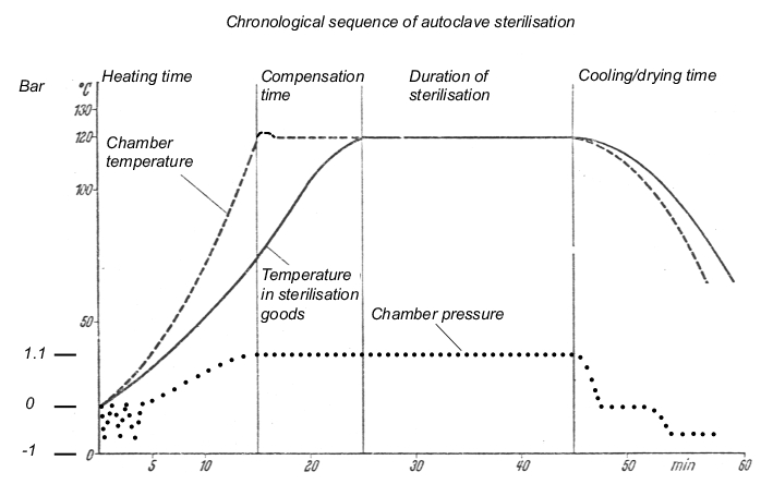
The steam sterilisation process has to fulfil three conditions: The steam must be saturated, be under positive pressure, and be kept at a temperature of at least 121 °C. It must be possible to maintain these conditions for any chosen length of time. In order to fulfil the conditions, "chamber autoclaves" (steam sterilisers) are used. The steam sterilisation procedure consists of the phases described in figure 12.F-1.
| Phases in steam sterilisation |
|---|
|
The sterilisation process using a steam autoclave is described using a time-temperature curve (see figure 12.F-2).
|
12.F.2.1 Sterilisation
The aqueous solutions, immediate containers or accessories that are to be sterilised must come into contact with a saturated steam phase or a self-generated steam phase (for solutions). Saturated steam refers to steam that is in a state of equilibrium with its liquid, which means that if liquid condensate is present, the steam is definitely saturated. Saturated steam has a particular pressure at each temperature. This physical relationship means that in the case of defects in measuring technology, it is possible to evaluate the sterilisation conditions on the basis of the pressure course or temperature course.
In order to establish the steam/steam air or hot water sprinkling conditions, any air present in the autoclave at the beginning of the process must be removed by suction. To do this, a circulation pump is used to create a vacuum of <100 mbar (abs). The chamber is then filled with saturated steam via the heating mantle, followed by aspiration once more (in three to ten cycles), which takes into account the different designs and uses of the steam steriliser and the type of product undergoing sterilisation. Subsequently, saturated steam is supplied to a positive pressure of approx. 1.1 bar. The resulting temperature corresponds to the steam pressure-temperature curve.
- 120 °C = 1.9854 bar
- 121 °C = 2.0492 bar
- 122 °C = 2.1145 bar
- 123 °C = 2.1816 bar
- 124 °C = 2.2504 bar
Based on requirements of the various pharmacopaeiae (not lower than 121 °C) and according to USP (±1.0 °C deviation in the empty chamber), this results in a pressure regulation range of 65.3 mbar (from 121 °C to 122 °C).
- 121.1 °C = 2.0556 bar
- 121.5 °C = 2.0811 bar
- 122.0 °C = 2.1145 bar
- 122.5 °C = 2.1470 bar
The different loads of an autoclave (equipment, containers of varying sizes and mass) mean that different amounts of heat (in the form of saturated steam) are transferred to the sterilisation goods over differing lengths of time, and the resulting condensate is continually removed by condensate separators, the temperatures in the chamber and in the objects can change so quickly that controlling the steam feed using heat sensors becomes too slow. It is therefore necessary to control the steam feeding based on the pressure in the chamber. This provides immediate regulation and can be set to an accuracy of 0.1 °C = approx. 7 mbar.
It is then possible to measure the temperature in reference objects, in the chamber, and in the condensate outlet, the start of the sterilisation time from 121 °C, the end of the cooling phase etc., with double Pt100 heat sensors. A temperature measurement is then sent to the measuring equipment and the recorder on the autoclave. The parallel measurement is used as a safety or comparison measurement (or for monitoring purposes) and leads to a measured value printer with F0 calculation. A prerequisite condition for the start of the time period for the sterilisation phase is a temperature of at least 121 °C at the coldest reference point in the sterilisation goods (for example, inside a bottle or in a filter, valve, or tube).
Figure 12.F-3 provides an overview of the specifications for sterilisation time in the various pharmacopoeias.
| Pharmacopoeia specifications for sterilisation time |
|
|---|---|
European pharmacopoeia, JP, BP |
at a minimum of 121 °C for 15 min |
DAB, EP |
121 °C for 15 min with ± 2 °C and ± 10 kPa measured in the coldest point of the autoclave |
USP |
Using a temperature not less than 121 °C ..... the F0 concept may be appropriate........ |
12.F.2.2 Drying
After the sterilisation phase, there follows a drying phase at approx. 70 °C (temperature of the steriliser mantle) under a vacuum.
In the sterilisation of closed containers (ampoules, bottles), the high pressure built up inside the container (approx. 4 bar due to the expansion of air in the empty space above the solution) has to be accounted for since, as the steam pressure in the chamber is reduced in the cooling and drying phase, a support pressure of up to 2.5 bar is built up using compressed air. This prevents bottles and ampoules from exploding and seals from deformation due to an excessive pressure differential. In the case of open piston stoppers in prefilled syringes, it is particularly important to control the support pressure to minimise any movement of the piston stopper in the glass object during the sterilisation and cooling phase.
The necessary duration of the drying phase for the relevant load and features of the sterilisation goods (for example, membrane filter layers require very long drying times) must be established in the performance qualification (PQ) and described in an SOP. Figure 12.F-3 shows the requirements of the pharmacopoeias for sterilisation time.
12.F.2.3 Sterilisation kinetics
The inactivation of microorganisms follows the kinetics of a first-order reaction, which means that the number of microorganisms inactivated within a given time is always proportional to the number of existing microorganisms that are still alive (see figure 12.F-4).
| Microbial reduction and survival rate |
|---|
log Nu = - U/D + log No Nu = Microbial count after U minutes No = Original microbial count D = Decimal reduction time for the relevant temperature |
Definition of the symbols used to describe sterilisation kinetics:
n: Number of organisms, expressed as CFU (colony-forming units), also known as microbial count.
D value: If microorganisms are subjected to heat with a higher moisture content (at a constant temperature), the microbial count decreases in relation to time. The D value is the decimal mortality rate in minutes at a given temperature, or the time in minutes that is required to kill 90 % of the spores or vegetative cells of a specified microorganism at a given temperature. The D value always refers to one temperature and one microbial species, for example, D121 °C Bacillus subt. Figure 12.F-5 shows an example of how to calculate the D value.
| Calculating the D value |
||
|---|---|---|
Sterilisation conditions (moist heat) |
Microbial reduction |
D value |
100 min at 100 °C 10 min at 110 °C 1 min at 120 °C |
104 -> 103 104 -> 103 104 -> 103 |
100 min 10 min 1 min |
Z value: value in degrees Celsius that causes a change in the decimal D value (or: the change in temperature that causes the D value to change by a power of ten). The Z value is also defined as the relative resistance of a given microorganism against different temperatures. The Z value for Bacillus stearothermophilis is 10 °C.
F0 121 °C: The total amount of heat that acts on the sterilisation goods during a sterilisation process, adjusted according to the relevant temperature (here 121 °C) in min, or the temperature course of the whole sterilisation curve including the heating and cooling phase. Since the calculation is of American origin, the specification is 250 ° Fahrenheit, which corresponds to 121.1 degrees Celsius.
For example: The F0 value specifies the sterilisation time (min) at 121 °C or the corresponding sterilisation time (min) at 121 °C for sterilisation temperatures above or below 121 °C. The calculable F0 value can be used to compare sterilisation procedures performed at temperatures above or below 121 °C in terms of the microbial killing effect of the standard autoclave at 121 °C.
At a constant temperature, the following applies: 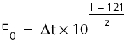
t = sterilisation time (min)
T = sterilisation temperature(°C)
z = 10 °C.
For a fluctuating temperature, the following applies: 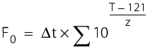
For example:
F0 value of the procedure for 60 min at 105 °C F0 = 60 x 10 ( 105 - 121)/10 F0 = 60 x 10 -16/10 F0 = 60 x 10 -1.6 F0 = 1.507 |
F0 value of the procedure for 20 min at 120 °C F0 = 20 x 10 (120 - 121)/10 F0 = 20 x 10 -1/10 F0 = 20 x 10 -0.1 F0 = 15.88 |
With reference to the calculation basis of 121.1 °C, which is also the basis for all automatic programs for F0 calculation, the following example uses realistic setting values based on 121.5 °C and 20 min sterilisation time:
F0 value of the procedure for an actual 21.5 min sterilisation time at 121.8 °C.
F0 = 21.5 x 10 (121.8 - 121.1)/10
F0 = 21.5 x 10 (0.7)/10
F0 = 21.5 x 10 0.07
F0 = 25.26
12.F.3 Qualification of a steam steriliser
The operation of a steam steriliser must ensure that the objects or solutions treated in the system achieve the required result - i.e. they are free from living microorganisms. This can be ensured by technical design and qualification.
The requirements are described in a user requirement (see chapter 6.D Design qualification (DQ)). The aim of qualification is to provide evidence that the steam steriliser meets the defined requirements in terms of design, function and operability. Inspection by the authorities concentrates in particular on the points named in figure 12.F-6.
| Test points for inspections |
|---|
|
When selecting a design (steam sterilisers are not constructed according to customer requirements, but are, at most, modified by manufacturers of these devices), it is important to be clear about the requirements and transfer these to a technical specification. A qualification plan must be created in which the qualification process is described (see chapter 6 Qualification).
The qualification activities must be monitored and checked by an independent department or person who is responsible for ensuring that they are processed correctly, and attests to this with a signature. The operator is responsible and must be sure that the qualification process has been performed correctly. To realise this responsibility properly, the responsibilities must be defined in the qualification plan (see figure 5.D-19).
System functions and process steps can be classified as critical or uncritical using a risk analysis. A risk analysis can form a very useful basis for qualification and validation plans (see chapter 10.D Methods of risk management).
12.F.3.1 Installation qualification
The execution of the tests is described in detail (see figure 12.F-7), to enable exact replication of the same tests in the future. Measured values must be recorded in the test protocol and documents (printouts, diagrams, etc.) must be included as attachments.
| Tests in installation qualification |
|---|
|
Calibration of measuring points
As a part of preparation for operational qualification, an initial calibration of the measuring equipment should be performed before start-up of the steam steriliser. The measuring points defined in the IQ, the type of measurement, operating range, adjustment thresholds, calibration intervals and accuracy categories must all be included in the calibration for process validation (see figure 5.D-16). Quality-relevant measuring points in steam sterilisers are as follows:
- Temperature (chamber, reference object, condensate)
- Time
- Pressure (positive pressure and vacuum).
Measured calibration values must be compared with reference measuring systems from a higher class. To perform a reliable calibration, for example, a three-point calibration is performed. For a steam steriliser, these are room temperature 20 to 25 °C, a drying temperature of approx. 70 °C, and the sterilisation temperature of 121 °C. These three measured values are compared to the reference equipment (in this case, a tested Hg thermometer with 1/10 °C increments, tempered in an oil thermostat).
For values outside the acceptable measured value tolerance, the measuring chain must be adjusted and recalibrated. The operational qualification cannot take place until a successful initial calibration has been performed. In general, this results in 10 to 15 temperature measuring points for calibration.
Heat sensors
Pressure and vacuum resistant control heat sensors are used (type Pt 100) with feeds that are fed into the steam sterilisation chamber, where they are positioned according to a distribution plan. The feeds are connected to a measuring point recorder of the appropriate quality grade.
If using tracers (for example, made by Ball), the cables become unnecessary, since these devices store temperature values and can be imported to a PC before and after they are used. The calculation program can be used to calculate and print F0 values, curves, numerical values, etc., as required. In both procedures, the control heat sensors must be calibrated. In general, twelve control heat sensors are tested in accordance with an SOP, before and after the validation measurement at 121 °C (not a 3-point measurement) in the oil bath thermostat. The number of heat sensors depends on the trays in the steam steriliser, but in order to provide a representative heat distribution test, must cover the whole space divided into parts of approximately the same volume (see chapter 12.F.4.2 Loading configurations). In productive operation of When operating a steam steriliser in production, three heat sensors are absolutely necessary:
1. A "product sensor" at the coldest point
2. A free chamber sensor
3. A heat sensor in the draining condensate
Modern sterilisers also use as many as twelve heat sensors in production operations. The maximum permitted deviation is ± 0.5 °C. A correction factor is determined from the average values before and after as follows:
Before validation, a temperature of 121.0 °C is set in an oil bath (Hg thermometer stem corrections must be taken into account). The heat sensor to be used is inserted into the oil bath and shows, for example, a temperature of 121.2 °C. The determined deviation is +0.2 °C. This sensor is then used to measure the temperature in the steam steriliser. After this measurement, the deviation in the oil bath is determined once again. This results in, for example, 121.4 °C. The deviation is therefore +0.4 °C. The resulting correction factor is +0.6 °C divided by 2 = +0.3 °C.
All calculations for this sensor are performed with a correction of -0.3 °C, because the measured values are changed by +0.3 °C during the sterilisation phase. The data is documented in a calibration record.
Chamber pressure transmitters
The chamber pressure transmitters are tested against a control device at pressures of 1.1 and 2.1 bar (abs). They must meet the requirement of £0.05 bar pressure differential. The data is documented in a calibration record.
12.F.3.2 Operational qualification
After the DQ and IQ, the equipment and function of the steam steriliser are tested using the defined process parameters. This test is the operational qualification (OQ) for the device. In the operational qualification, all the operating states of the steam steriliser are simulated to their limits (worst case), and the results documented (see figure 12.F-8).
| Test points in operational qualification (extract) |
|---|
|
Testing heat distribution
During operational qualification, the three empty chamber sterilisation runs in a full cycle must show an even heat distribution in the empty chamber. In addition, there must be no cold spots (average value of the temperatures from all control sensors (see chapter 12.F.4.2 Loading configurations) <1 °C must be determined. The coldest spot is established as follows: One individual measured value is -1.4 °C below the average value of all the heat sensors used, for example, 122.4 °C (measured value = 121 °C). This means that a cold spot would exist in this position, as the permitted deviation limit is only 1 °C.
This test proves that the construction of the steam steriliser, the distribution of its steam inlets and distance of the storage surfaces from the "cold" doors (not insulated by the mantle) do not form condensation surfaces for the steam, which may affect the temperature. Since all common steam sterilisers are constructed in a way to specifically prevent these influences, deviations with cold spots when examining empty chambers tend to be theoretical.
Function tests
In addition to calibrations, the function tests listed in figure 12.F-9 are also performed. These tests should be repeated in process validation, since some time may have passed since the OQ and changes may have occurred.
| Function tests |
|
|---|---|
Recorder feed of the external device |
|
Function check of the steam steriliser - time measurement |
|
Tightness test |
|
Inspection of media quality
During qualification, the quality of the pure steam and the air used to ventilate the autoclave is also tested. This test is also repeated during process validation, as the steam system must have undergone a separate qualification and process validation. The data from these studies can be used. However, current values must be available from monitoring or must be determined during process validation of the steriliser. The requirements for pure steam are summarised in figure 12.F-10.
| Requirements for pure steam |
|
|---|---|
Full analysis of the pure steam condensate |
Corresponds to WFI |
Particle measurement |
£ 25 P/ml ³ 10 mm |
CFU determination |
£ 10 CFU/100 ml |
Endotoxin determination |
< 0.25 EU/ml |
Before entering the chamber, the steam is filtered via 13 mm and 0.1 mm particle filters (for example by Pall, Composit 0.1 mm). Air is guided over vent filters, before it enters the chamber. A retention rate of 0.2 mm is achieved, for example with the Pall filter MCS 4440V002. Filter integrity tests are executed and documented before and after the validation activities.
Following successful completion of qualification, the qualification report (consisting of an introduction, results and summary/evaluation) is created and released by the person responsible for validation and/or head of production or quality control, and by quality management (see chapter 6.C.3 Qualification report).
12.F.4 Validation of the steam sterilisation process
The first step after qualification is to compile the validation protocol based on internal company guidelines. The validation protocol formulates the aim to provide evidence that a reproducible sterilisation process is achieved in the steam steriliser under overkill conditions.
| Extract from a validation protocol |
|
|---|---|
Responsibilities |
|
Person responsible for validation |
Head of Production, head of quality control |
Validation manager |
Project manager |
Validation team |
Staff of the unit (users) QA staff |
Responsible for implementation |
Staff of the unit (users) |
|
|
Overkill conditions: by using bio-indicators and adjusted, shortened sterilisation time (partial cycle), to provide evidence that the process parameters for the worst case of 121 °C and 20 min overkill conditions (F0 12 min/D121 °C = 1 min) are achieved. |
|
A prerequisite for executing the validation is the employment of qualified personnel, and proof that the systems and test equipment are qualified for the intended purpose, and the measuring equipment is calibrated.
12.F.4.1 Description of equipment and process
The steam steriliser supplied by XYZ is installed in building 000 in cleanliness grade XY. In most cases, autoclaves are used as pass-through autoclaves with two doors leading from one cleanliness grade to another cleanliness grade. The steam steriliser is used to sterilise final containers and accessories (for example cylindrical ampoules, rubber stoppers, and crimping caps in sterile bags or sterilisation boxes). The sterilisation is performed in accordance with the relevant SOP (see figure 12.F-12 and figure 12.F-13).
| SOP for sterilisation in the steam steriliser (autoclave sterilisation) |
|---|
Author: Checked: QA approval: Released by head of production: Signatures:......Valid from: |
Contents: 1. Aim/Purpose 2. Responsibilities 3. Scope 4. Description of procedure execution 5. Documentation 6. Other relevant SOPs 7. Attachments |
1. Aim/Purpose 2. Responsibilities 3. Scope 4. Description of procedure execution
Media (pure steam, compressed air, drinking water, purified water/WFI) |
Process
Remove the sterilisation goods and check the sterile packaging is undamaged and the indicator turn over (marks the goods as sterilised), if applicable. In all other cases, the sterilised products must be assigned a "sterilised" label. |
5. Documentation
|
6. Other relevant SOPs For example: Recorder evaluation, SOP XYZ Tightness test SOP XYZ Use of filter SOP XYZ Sterilisation of filters and tubes, SOP XYZ etc. |
7. Attachments Loading configuration Program course for device and valve function |
The steam steriliser consists of the central pressure chamber with two doors surrounded by a heating mantle, and peripheral measuring and control devices. When attaching control measuring equipment to the steam steriliser and bioindicators in the immediate vicinity, the whole space in which the goods to be sterilised are positioned should be taken into account. This usually means that several storage levels are set up in the steam steriliser, so that a number from 10 to 12 positions must be measured in addition to the actual chamber or condensate sensors. For the validation of steam sterilisers for final containers (for the sterilisation of filled ampoules and bottles), the procedure is the same as the validation protocol above, but the temperature is always measured in the objects (bottle or ampoule or reference object). This includes the bioindicators. This ensures that the different heat-up times and cooling phases of small and large volumes are taken into account. This must include the very long heat-up times of filter housing, steel mantle tubes and media fill solutions in open steel pressure containers.
The sterilisation temperature of ³121 °C to 122.5 °C is determined using the chamber sensor and the sterilisation time is selected using a timer switch. The sterilisation is regulated based on pressure in accordance with the saturated steam curve. The temperature, time and pressure are recorded using a multi-channel recorder. More detailed technical information (for example, the electrical technology description of the control loop) is available in the qualification documentation.
The three validation runs for each loading configuration follow the usual sequence of operation for a steam sterilisation process (see figure 12.F-13).
| Sequence of operation |
|
|---|---|
Program selection |
Vacuum test Self-cooling Drying |
Pre-heating phase |
Opening the steam feeding Steam flows into the heating mantle and heats up the steriliser in advance (all parts of the system must be at operating temperature). During operation, a "short sterilisation" of approx. 5 min is carried out, and an equipment check is performed at the same time. The pre-heating phase is complete when the heating mantle has a steam pressure of approx. 0.3 bar. |
Load the steriliser |
|
Close and seal the steriliser (manual or automatic, depending on the model) |
|
Start |
|
Ventilation/pre-vacuum |
Evacuation of the pressure chamber to £ 150 mbar |
Sterilisation |
Steam flows at set intervals via the heating mantle into the pressure chamber until the sterilisation temperature is reached. Automatic start and processing of the preset sterilisation time. |
Pressure release by self-cooling |
After the sterilisation phase, in the program step "pressure release", the autoclave naturally becomes depressurised as the steam feeding is stopped and due to natural cooling. |
Drying |
The steam is released from the chamber and the chamber is evacuated (£ 150 mbar). The drying phase runs for the set time at a chamber temperature of approx. 70 °C (indirect heating via the heating mantle). |
Final ventilation |
The final ventilation is performed via two consecutive sterilised vent filters with a pore size of 0.2 mm. |
In the program for performing the vacuum test (leak test), the chamber is evacuated to a pressure of £65 mbar (abs). The pressure subsequently must not rise to more than 80 mbar (abs) within 10 minutes.
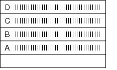
12.F.4.2 Loading configurations
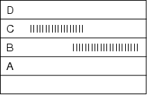
During validation, all loading configurations that are possible during routine operation are tested, as the success of sterilisation greatly depends on loading. The different loading configurations and the relevant positions of the heat sensors and bioindicators is shown below.
X = external heat sensor (Pt100), tracer
0 = Bioindicators
K = Chamber sensor
I = Object to be sterilised (filters, tubes, accessories)
Empty steam steriliser
View from front |
|
|
View from above |
4th layer (top) D |
|
3rd layer C |
|
|
2nd layer B |
|
|
1st layer (bottom) A |
|


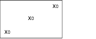
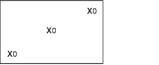
Steam steriliser with minimum loading
View from front |
|
|
View from above |
4th layer (top) D |
|
3rd layer C |
|
|
2nd layer B |
|
|
1st layer (bottom) A |
|


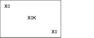
Steam steriliser with maximum loading
View from front |
|
|
View from above |
4th layer (top) D |
|
3rd layer C |
|
|
2nd layer B |
|
|
1st layer (bottom) A |
|

12.F.4.3 Bioindicators
Bioindicators provide an additional check of the success of sterilisation. These are marketed ampoules or spore strips with defined germ solutions (microbial count and type) (see figure 12.F-14). These are positioned as described in chapter 12.F.4.2 Loading configurations. After use, the bioindicators must be incubated for 3 to 5 days at 56 ± 2 °C (ampoules are directly incubated, spore strips are placed in a culture broth). No microbial growth must be visible on any ampoules or spore strips (see chapter 12.H.6 Reading and evaluating).
| Bioindicators |
||
|---|---|---|
For example, Attest‚ ampoules supplied by 3M |
For example, spore strips supplied by BAG |
|
Test organism: |
Bacillus stearothermophilus |
Bacillus stearothermophilus |
Batch: |
see certificate |
see certificate |
D121° value |
see certificate |
see certificate |
Insemination: |
see certificate |
see certificate |
Expiration date: |
see certificate |
see certificate |
12.F.4.4 Determining the sterilisation time
To check the microbiological effectiveness, only bioindicators with an F0 value of <10 min are available. These indicators cannot be used for evidence of an overkill procedure (³12 min). The routine sterilisation time is therefore reduced to a partial cycle.
Using bioindicators with a known insemination of Bacillus stearothermophilus, together with the choice of a suitable reduced sterilisation time (partial cycle), three validation runs are performed for each loading configuration. For revalidation the recognised procedure is to use one run with minimum load plus three runs with maximum load. Spore strips with a sufficient insemination and D value can be used in a full cycle (for example, insemination 2.58 x 10⁶ CFU, D value 2.1 = F0 of 13.56 under conventional conditions T = 121.1 °C, D121 °C = 1 min). The principles listed in figure 12.F-15 to figure 12.F-17 are used to calculate the sterilisation times.
| Determining the minimum sterilisation time |
|---|
F = n x D121 |
D121 = Decimal reduction time (TReference = 121.1 °C) F = Effectiveness of the sterilisation process n = Original microbial count (log 10) |
| Determining the maximum sterilisation time |
|---|
F0 Overkill /F0 Part = tTot /t Part |
F0 Part = Effectiveness of the partial cycle (see bioindicator) tTot = Total sterilisation time tPart = Maximum partial cycle time F0 Overkill = 12 min |
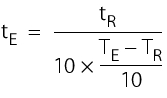
| Sterilisation times for equivalent temperatures |
|---|
|
tE = Sterilisation time for equivalent temperature tR = Sterilisation time at reference temperature (for example, F0) TE = Equivalent temperature TR = Reference temperature (121.1 °C) |
12.F.4.5 Executing the validation
The particular configuration (size, internal construction of the chamber, trays, inlets and outlets) is used to determine the minimum and maximum (worst case) loads based on the routine loading configuration with sufficient steam penetration. Whether sufficient steam has reached the sterilisation goods can be judged by the killing of the bioindicators: If no moisture is present, the required killing rates are not reached.
The steriliser temperature is between the permitted limits of 121 °C to 122.5 °C. The D value and the insemination of the bioindicator used (for example, Attest ampoules) together with the sterilisation temperature, are taken into account to determine the required sterilisation times (see figure 12.F-17). Some companies stop the sterilisation process after these calculations and once company-defined F0 values have been reached (to protect the active pharmaceutical ingredient being sterilised). The great advantage of calculating and determining F0 values is the provision of definitive data regarding the sterilisation robustness if the sterilisation time is slightly longer or shorter than the prescribed time for technical reasons. Since the realistic sterilisation temperatures only become evident during the actual sterilisation process, times must be prescribed for the temperatures 121 °C/122 °C and 123 °C. Once these temperatures and times are achieved, the operating personnel must terminate the sterilisation phase. The time of the partial cycle is measured when the coldest measuring point of the loading configuration (see chapter 12.F.3.2 Operational qualification) has reached 121 °C. Testing the heat distribution in the empty chamber during operational qualification does not usually reveal the coldest spot, due to the appropriate design of the steam steriliser. Deviations from temperature courses during the sterilisation process are only caused by the sterilisation goods, and evaluation and control of the sterilisation time for the sterilisation goods are therefore required, which should be established in process validation (operational qualification).
The documentation includes the following documents:
- Time-temperature-pressure record of the sensors installed in the steam steriliser
- Time-temperature record of the control heat sensor
- Results of the evaluation of bioindicators following incubation
- Certificates of the bioindicators
Once the sterilisation process is complete, the data is evaluated. In terms of temperature, the evaluation is based on measured data once the stable plateau phase is reached. The temperature-time curves (see figure 12.F-2) should be evaluated in the final third of the partial cycle time.
- Assessment of saturated steam conditions (temperature, pressure)
- Requirement: pressure-temperature combination in accordance with the saturated steam curve
- Assessment of the required heat penetration (temperature, time in the objects)
- Required temperature ³121 °C, sterilisation time within the corresponding min, max partial cycle time
- Assessment of the measurement results from the device measuring equipment compared to the control measuring equipment (evaluation of heat-up time)
- Assessment of effectiveness using physical data (F0)
- Assessment of bioindicators for sterility (in parallel with positive controls)
- Assessment of the sterilisation process (according to PDA monograph no.1, relating to calculation principles for microbial reduction)
The microbiological effectiveness is calculated according to the formula in figure 12.F-18.
| Calculation of the microbiological effectiveness of the partial cycle (F) |
|---|
F = D x (log10 A - log10 (2.303 x log10 n/q)) |
A = Insemination of bioindicator n = Total no. of bioindicators used q = Bioindicators with no growth (negative result) |
Testing of ventilation piping
Replacement of the vent filters (after 6 or 12 months) means that the ventilation valve and the pipes need to be sterilised. Attaching a spore strip in the ventilation piping provides evidence of a 12-log microbial reduction in full-cycle sterilisation. After incubation of the bioindicator, no growth must appear.
Reproducibility
The reproducibility is checked, for example, under the following conditions:
- Temperature: 121 °C (lower permitted limit)
- Pressure: 2.1 bar (abs)
- Time: 21.5 min
The following requirements must be fulfilled:
- The assessment should be carried out using measuring data determined after 121 °C has been reached.
- Time, t: ³ 20 min and £ 23 min
- Temperature, T: 121 °C to 122.5 °C
- Pressure, p: Saturated steam conditions (T, p)
- Assessment of the evaluation and control of the recorder chart (in accordance with company SOP).
- Documentation: Time-temperature-pressure records from routine sterilisations.
Completion of validation
The results of the tests must be recorded in a validation report. When the validation process is complete and all results are positive, the steam steriliser can be released in the described scope for one year. After this time, revalidation is required. Requalifications must be performed if technical changes are made to the steam steriliser (Change Control).
Despite successful validation of a sterilisation process and a the understanding and proof of microbial reduction theories parametric release is not common practice (see chapter 12.H.1 Parametric release). The deciding factor is that in the case of technical deviations, no biological verification (sterile test) is possible and the batch would be lost.
Summary Due to the importance of steam sterilisation in the production of sterile products, the qualification and process validation should be planned and executed based on a background knowledge of sterilisation kinetics. It is important to pay particular attention to the accuracy and reliability of the temperature measuring equipment and pressure display and regulation. Monitoring and documentation of the sterilisation conditions by personnel and appropriate measuring point recorders help to ensure reliable processing. The loading configurations selected in process validation must always be adhered to in operational processing. If the loading configuration of an autoclave is changed, a change control procedure and repeated process validation are required. The bioburden before sterilisation should be established. Limits on the sterilisation time beyond the relevant legal regulations are defined by the manufacturer during the development and introduction of a product. Monitoring with bioindicators should be carried out based on process validation. |
