Manufacturing the solution
Here you will find answers to the following questions:
|
12.C.1 Starting materials
A solution is a transparent liquid. It contains active pharmaceutical ingredients and excipients, dissolved in a solvent. The dissolved substances can exist in several different forms:
- Ion disperse: the solution contains ions as in an ionic solution.
- Molecular disperse: the solution contains molecules, as in a non-ionic solution (particle size 10-8 cm).
An important feature of a solution is that the dissolved substances are returned to their initial state when the solvent is removed.
The EU-GMP-Guideline does not define any values for microbial purity, but requires that a solution should "contain the minimum of microbial impurities". The USP requires that the necessary precautionary measures are implemented to reduce the bioburden to an acceptably low level before sterilisation. For solids, a value of 100 CFU/g is standard practice for solvent production with subsequent steril filtration and sterilisation. In aseptic processing, sterilised or sterile filtered starting materials must be used.
The most common solvents used in pharmaceutical manufacturing are:
- Purified water and water for injection (WFI)
- Alcohol
- Oils
- Mixtures of various solvents
Purified water is used in cleaning as rinse water for containers and equipment after use, and as rinsing water (particle filtration 2 mm < 10 mm) for immediate containers, immersion basin water, and splash water during the washing process. There then follows the final rinse with WFI (see chapter 5.A Water types).
Active pharmaceutical ingredients can be materials from natural sources or substances manufactured by gene technology or synthetic methods.
Excipients include all components of the preparation that are necessary in order to deliver the active pharmaceutical ingredient to the patient in a tolerable manner, in accordance with its dosage form.
In accordance with the EU-GMP-Guideline, active pharmaceutical ingredients, solvents, and excipients are all classified as starting materials.
12.C.1.1 Rooms used for weighing
In general, materials should be weighed in clean areas, to prevent changes to their initial purity. They should be weighed in completely separate areas according to their biological activities (separate fume cupboards, air flow pattern and accumulation of dust) (see chapter 11.G Weigh-in). Grade D, C or A is required, depending on the starting purity (<100 CFU/g to sterile). Sterile substances are weighed in sterilised containers (such as beakers) under grade A (clean bench) conditions, and transferred to solution containers under cleanliness grade A. Here, the background environment must comply with cleanliness grade B.
Due to particle shedding (from solids) in the air, and other possible effects on people, handling of these substances is subject to general safety regulations. When weighing sterile substances, personnel clothing complies with cleanliness grade B, and the clothing also provides personal protection. In cleanliness grade D, a dust mask/safety spectacles may also be necessary to meet safety requirements.
"Weighing boxes" are also available, which have a specific exhaust mechanism attached to the balance and negative pressure in relation to the surrounding cleanliness grade. These can be useful to prevent cross-contamination.
The substances to be used are specified in the processing instructions.
Starting materials are labelled with a designation and a company-specific ID number, which details the required specification of the substance, and usually the current test results regarding approval for use in drug product manufacturing. Only released substances should be used for further processing (see chapter 14.J Batch release).
12.C.1.2 Processing instructions (manufacturing instructions)
Approved manufacturing instructions are required for all products and each batch siye to be manufactured. These are used to develop processing instructions that contain detailed handling steps in accordance with the available equipment, and processing steps (see chapter 15.C Batch documentation). IT-based documentation systems and a change management procedure (see chapter 19.C Change control) are designed to ensure that correct current specifications are always compiled. Documentation in accordance with GMP requires that each individual step in the manufacturing process is recorded in writing, if possible at the time of the activity, and is evaluated and initialled by the responsible persons, for example in a doer/checker procedure. The "Doer" adds their initials to confirm the handling, and the "Checker" checks and confirms the whole protocol based on specifications and the weighing record, for example, checking the printed balance quantities and the results of identity checks.
During the course of solution preparation, the equipment used means that a large number of processing substeps take place in different locations, using different equipment, performed by different people and at different times. It is therefore practical to identify these individual activities numerically and keep the documentation (for example, record of a sterilisation process of filters in autoclaves, doer/checker assessment) at the location in which the activity is executed. Only the numerical ID of the activity is then entered in the processing instructions, together with the date and initials of the employee responsible.
It can also be helpful to structurally divide the processing instructions into different sections and, once they are completed and approved, send the completed sections (each with separate page numbering) to the different locations involved in the procedure, or even generate them on a computer system in each location. Once each activity is completed in the separate locations (e.g. weighing, machine preparation, washing of containers, in-process checks), the completed sections are combined and form the processing protocol. A procedure of this type ensures that the relevant part of the processing instructions is always available at the correct location and at the right time.
12.C.1.3 Weighing of starting materials
The header section of each printed section of the processing instructions includes the date of printing, the name of the preparation, the number of the applicable manufacturing instructions, the batch number of the batch, the batch number of the filling, and company-specific ID numbers for pharmaceutical tracking based on the use of components and the final container. These ID numbers are also used for business monitoring and accounting.
An example of the first line of a weighing record, starting with the first substance in the order in which they are used in the batch, is shown in figure 12.C-1.
| Example weighing record |
||||||
|---|---|---|---|---|---|---|
Item no. |
Name |
Article no. |
Release/experiment no. |
Required amount |
Actual initial weight |
Doer |
0001 |
xyz |
111111 |
1234567890 |
1000.000 g |
.... . ... g |
....... |
A sample should be taken from each individual pack of a substance and checked for identity. The result must be attached to the weighing record before the substance is further processed. If several packs of the same substance are weighed in initial weighing, all the results must be documented. The test method is selected by the responsible unit, as long as it is validated or is a standard pharmacopoeia procedure.
The substance can be weighed in containers made from various materials (stainless steel, plastic, glass, plastic bags, etc.) that have been cleaned using a validated procedure, or materials of a known cleanliness grade (plastic bags). All weighed substances are labelled to indicate their application (substance name, quantity, for preparation XY, batch Z, etc.). The individual containers should be sealed and secured, and all containers for one batch should be stored together.
12.C.2 Solution batch
In accordance with the processing instructions for the batch (execution in cleanliness grade D or C), a visual control should be performed for each step to ensure that the cleaning and sterilisation steps for the devices and filters have been correctly performed and the labelling is correct, and the person responsible for the control then enters their name in the designated field. The solvents are generally placed in the reaction vessels in advance. This is performed in the form of a weight or volume measurement.
Each operation (in accordance with the specified SOP) is confirmed by the employee's initials in the processing instructions immediately after it is performed, and any printouts from balances or measuring instruments are attached to the processing instructions.
The addition of previously weighed substances to the batch, and the compliance with specified parameters, methods, and timescales (for example temperature, stirring duration, stirrer revolutions, pressures, reaction times, sampling and measured values (such as pH or density), should be checked, monitored, and confirmed by two members of staff (doer/checker principle). Figure 12.C-2 shows an example of how the documentation can be structured.
| Division of processing instructions into Action, Check and IPC (independent of processor) |
|---|
Activity _xyz___ acc. to SOP__xxx_________________________________________ Name__Doer_______Comments____________________________________________ Activity _xyz_____ acc. to SOP_xxx____Target:_____ Actual:______ Result________ Name__Checker___ Comments___________________________________________ IPC Process laboratory: For activity _xyz____ Target value:__0000____ Actual value:_____ Result__________ Name__Doer_______ ___Checker____ |
One exception is the bulk production of WFI, which is used in the manufacturing of parenterals and for the final rinsing of equipment, containers, and final containers. In this case, compliance with the specification (see chapter 5.A Water types) must be proven by monitoring at the WFI manufacturing plant and point of withdrawal. The test for the presence of endotoxins in the WFI in the reaction vessel, which provides a relatively quick result (residue limit for WFI <0.25 EU/ml), also provides a partial conclusion to be drawn regarding the purity of the vessel.
Further subsequent steps in the manufacturing process are listed and processed in the same way. At the end of the process, the target value for the batch according to the recipe and actual value are compared, and expressed as a percentage yield. The yield must lie within a previously specified target range. If the value is not within this range, a plausible explanation for the deviation must be provided (see figure 12.C-3).
| Yield outside the specified range |
|---|
Example 1: |
Example 2: |
Example 3: |
Solids should be added to the reaction vessel with the minimum possible generation of dust (extra exhaust in order to exclude cross-contamination). The technology of absorption of solids should always be preferred if the flow properties of the substance and the diameter of the pipes in the container permit.
When transporting solutions through pipes, due to possible sealing problems and particle shedding, no pumps should be used, but filtered nitrogen or compressed air should be used instead.
SOPs for solution manufacturing should not only describe consecutive operations and activities, but should also require checks of the previous steps for equipment and accessories. Any anomalies and irregularities must be recorded and discussed.
In solution preparation, the reliability of the preparation, labelling, and the sound functioning of all the necessary equipment and tools are particularly important. In the case of malfunctions, replacement devices must be available that have been cleaned and sterilised. Experience shows that the time required for a failure of this type in the process is around three hours. If this happens, the process flow of the scheduled batch does not correspond to the planned time schedule, and therefore requires a "procedural deviation" report (see chapter 11.K Deviations).
If expected values from the manufacturing instructions (processing instructions) are not met or, for example, there is a loss of yield, this leads to an OOS result (see chapter 14.H Out-of-specification results). This may be associated with special checks to provide evidence that the quality of the preparation has not been impaired. It also initiates the long-term elimination of the cause of the failure and training of personnel.
Attention to detail in the initial phase of a manufacturing process can therefore have a decisive influence on the reliability of a process flow. Of course, this means that the responsible managers must always be available at these times and contribute towards the problem solution. Figure 12.C-4 lists some examples of weak points that can lead to OOS results.
| Weak points that can lead to OOS results |
|
|---|---|
Failure |
Cause |
Stiffness/blockage of plug and screw connectors and valves |
Damaged screw thread, damaged or ageing seals, not changed regularly |
Leaks in piping, equipment, and containers |
Assembly errors: Incorrect, missing seal, incorrect mounting direction |
Irregular filtration times, low measurement recordings |
Incorrect pore size of the filter, possible substance properties, defective pressure readings, recording equipment not monitored after the start phase. |
Sampling is a special case. Here the problem is not only that, if insufficient care and attention is paid to all points (see chapter 14.A Sampling), an incorrect result is generated and then corrected on repetition, but that the significance of any results is affected. This means that for each subsequent sample taken from another batch, doubts may arise as to the accuracy of the found values. Any measures that are implemented are then incorrect; laboratory data is cast into doubt and time is spent searching for errors that do not exist. The method description for sampling, and compliance with the method are therefore of the utmost importance. For example, the sequence of valve operations should be described. If valves are opened to take samples, a defined quantity must be collected as a preliminary run (in a separate container). Subsequently - without moving the valve, let alone closing it and reopening it - the actual sample quantity is filled in the sample container. This prevents the rinsing of dead spaces in the piping/valve and the generation of false results.
Figure 12.C-5 to figure 12.C-7 list the processes involved in solution preparation in chronological order for products with and without final sterilisation.
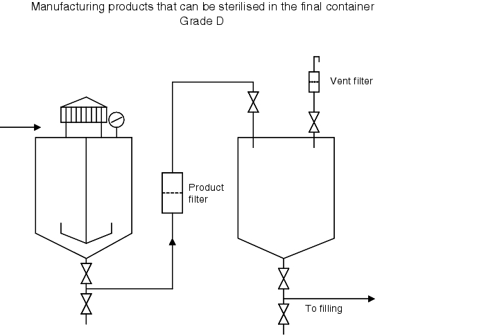
| Practical process flow for preparation of solutions (cleanliness grade D) that can be sterilised in the final container |
|---|
|
|
| Practical process flow for preparation of solutions that cannot be sterilised in the final container (cleanliness grade C) |
|---|
|
Cleanliness grade C
|
Cleanliness grade B
|
12.C.3 Testing the bioburden
Since, when manufacturing a solution, all surfaces, starting materials, surrounding air and other media (nitrogen, compressed air), as well as all personnel can be a source of microbiological contamination, the microbiological load of the product must be known before application of standard sterilisation methods. This enables you to ensure process reliability. An SAL (Sterility Assurance Level) of 10-6 is required, which means that the sterilisation conditions achieve a microbial reduction level in which only a maximum of one in one million objects may be unsterile.
For products sterilisable in the final container, the microbial count is determined using membrane filtration with the contents of a primary container, or 50 ml per container as a double determination. The limit is usually 100 CFU/ml (CFU = colony-forming unit), as is the case for purified water. There is no binding specification.
Aseptically processed products are tested in bulk. In this case, the residue limit is 10 CFU/100 ml (in accordance with CPM/QWP/486/95).
The use of rinsing or buffer solution during or after sample filtration (to eliminate the influence of starting materials on microbial growth) should be validated and incorporated in an SOP for the bioburden test. This should describe, for example, that after filtration of the sample solution for bioburden testing via a membrane filter with a pore size of 0.45 mm, the filter should be rinsed, for example, with 3 x 100 ml pH 7.0 sodium chloride peptone buffer solution. The rinsing procedure should also be validated for each specific product. The membrane filter should then be removed from the filter stand (obviously all carried out in cleanliness grade A, Clean Bench) and placed on an Agar culture medium for incubation. Casein soy peptone agar is used as a culture medium (for bacteria) and Sabouraud agar is for moulds.
If the limit is exceeded, further filtration should be performed. Since the result is not available until several days later, the process reliability can be calculated based on the batch quantity, filter surface, original microbial count, and validated separation rate (performed by the filter manufacturer for various germ species) (SAL 10-6) (see chapter 12.F Steam sterilisation).
12.C.4 Sterile filtration
Sterile filtration is the process of separating all microorganisms, apart from viruses, from a liquid. A sterile filter must block all microorganisms in a flow of liquid without affecting product quality.
12.C.4.1 History
Since the beginning of the industrial manufacture of medicinal products around 1900, three major methods of filtration have been pursued: porcelain, cellulose, asbestos filters, and since 1930, membrane filters.
After porcelain filters, cellulose asbestos filters (Seitz EK) were most common until the mid 1970s. Cooperation between filter manufacturers and pharmaceutical manufacturers enabled all disadvantages of the first generation of membrane filters, compared to cellulose-asbestos and porcelain filters, to be eliminated. Until the late 1960s, a pore size of 0.45 mm qualified as a "sterilisation filter".
These filters were qualified using a microorganism (Serratia marcescens) measuring 0.6 x 1 mm, which was at that time a standard bacteria in water and membrane analytics. As evidence showed that this microorganism occasionally penetrated the membrane with a test level of 104 to 106 per cm2, a pore size of 0.22 mm, for the effective retention of the 0.3 x 0.6 to 0.8 mm Pseudomonas diminuta/Brevundimonas diminuta (American Type Culture Collection (ATCC) as culture No. 19146), became the standard for the qualification of sterilisation filters.
12.C.4.2 Mode of operation
In general, it is assumed that the filtration effect is similar to the function of a sieve. Depending on their size, microorganisms are not let through the pores, but instead collect on the surface. This is the most important reason, but not the only reason why filtration works. This applies for geometric solid particles. Smaller particles and microorganisms are retained in the pores due to adsorption forces, depending on the pressure differential, flow rate, number of particles, surface tension, and degree of ionisation. The pressure differential is particularly important, since this must not lead to a deformation of the microorganisms. If the microorganism becomes deformed, it can become capable of passing through the pores and may be pushed through.
For the probability of bioburden reduction, the following factors must be taken into account:
- The greater the number of particles (including microorganisms), the greater the number of particles that are not retained. This means that the bioburden has a significant influence on the effectiveness of the filtration. The bioburden should therefore obviously be kept as low as possible. Germ species differentiation during monitoring is important in order to determine the size of the organisms. The data from routine monitoring (see chapter 12.G Microbiological monitoring) provides a clear picture of which organisms are present, which filtration pressure is required, and whether a slippage of microorganisms appears possible.
- The lower the pressure differential, the greater the probability of segregation of microorganisms.
- The longer the residence time of an organism in a pore, the more reliable its retention in the filter.
12.C.4.3 Materials, designs and properties
A sterile filter is defined as a filter capable of retaining 107 CFU of Brevundimonas diminuta ATCC 19146/cm2 of filter surface under specified conditions. Since the classification of a sterile filter is defined by the pore size (integrity test value), this has replaced the bacterial retention rate in production processes. A filter is classified as a "sterile filter" with a pore size of 0.22 mm. Filters with greater pore widths are simply membrane filters of different sizes (for example, 0.5 mm/1.0 mm/1.2 mm etc.). Due to the influences on the effectiveness of the filter as described above (see chapter 12.C.4.2 Mode of operation), the appropriate filter should be selected depending on the product.
Materials used include cellulose ester, nylon, polyester, polytetrafluoroethylene, polyvinylfluoride, polycarbonate, polypropylene, polysulfone, and polyethersulfone. In addition, hydrophobic or hydrophilic membranes are used.
Similar to the diversity of technical possibilities, filter housing, and mounts, the design of the filters are also varied: Disc filters, candle filters, and cartridges. Cartridges are supplied by the manufacturer and are membrane filter layers (0.2 mm, 0.45 mm, 1.2 mm etc.) that are pre-shrink-wrapped in a polypropylene housing, which are installed and used in piping following sterilisation. With disc filters, the users themselves have to fit membrane filter layers. This also applies for candle filters that have to be fitted in a filter housing (for example, those made by Sartorius and Pall).
It is important to note the possible release of extractables from the filter material, which could reach the product. Analytical methods should be available and the appropriate studies performed depending on the application of the filter.
It is also important to monitor the possible adsorption of active pharmaceutical ingredients from the membrane material, which may potentially cause changes to the product.
12.C.4.4 Filter integrity test
The filter manufacturers carry out a challenge test to prove the classification as a sterile filter, and, depending on the agreement, supply a certificate, an FDA number, and detailed documentation together with the filter.
The user is also obliged to validate sterile filtration with the product. The validation can be processed together with the filter manufacturer.
For integrity testing, manual or automatic tests are permitted. These tests must be validated. Filter manufacturers have also often developed their own test devices for their filters.
There are several tests that can be used to check the properties and correct functioning of membrane filters:
- Bubble point test
- Diffusive flow/forward flow test
- Pressure hold/decay test
The commonly used pressure hold/decay test is an indirect method of the forward flow test. This test provides a quantitative measurement of the sum of a test gas diffused through the membrane and the flow through each open pore.
Test equipment arrangement:
Pressure-gas - Valve (for separation) - Pressure/time recorder (mbar/s) - Filter -Room atmosphere.
In this method, the filter housing is placed under a certain pressure and then separated from the pressurisation system.
The compressed gas flowing through the membrane is quantitatively measured as a pressure drop in mbar/180 s. The pressure hold/decay test measures the diffused gas (air or nitrogen) through all moist pores and the gas flow through larger, non-moist pores, when a particular gas pressure is applied to a moist filter. The pressure drop is measured on the inflow side after disconnection of the gas supply. The pressure drop is a function of the gas flow through the filter and the volume of the filter system on the inflow side. The test also checks the integrity of the whole assembly, including seals. It is therefore important to eliminate faulty seals in order to conclude that there is definitely a problem with filter integrity.
If the pressure change is lower than the permitted maximum value, the filter has passed the physical integrity test. If the pressure drop reaches or exceeds the maximum value, the filter is defective. Investigations into the preparation processes of the filter must be introduced. The solution filtered through this filter must undergo refiltration (or another measure).
12.C.4.5 Executing sterile filtration
When performing sterile filtration of a solution, it is recommended to use a checklist (or a list included in the SOP) of all required components of the equipment and accessories, in order to ensure that no steps are omitted. All openings on equipment and accessories must be covered with sterilisation paper and secured with bio-indicator strips. All components must be labelled with the batch no. and drug product. The pore width and type of all filters must also be specified.
All components and devices (see figure 12.C-8) have been cleaned and sterilised in accordance with the SOP.
| Equipment for sterile filtration in cleanliness grade B: |
|---|
|
The assembly process must be performed from the cleaner grade B to grade C.
All accessory components removed from sterilisation devices (for example, pass-through autoclave from cleanliness grade D/C to cleanliness grade B) must be checked to ensure the integrity of the sterilisation seals and packaging, and transported together to the place of use.
When working under LF, the following must always be noted:
- The necessary interventions under LF are only permitted following disinfection of gloved hands.
- The work should always be performed from underneath the open surfaces exposed to the airflow
- Whenever possible, use tweezers or other utensils (use small tools and instruments so as not to disturb the LF).
The filter assembly is put together as described in figure 12.C-9.
| Filter assembly |
|---|
|
If using glass apparatus, the connection can also be made using glass olives and tube material.
The sterile connection from the filter to the storage container has now been established. The container for the sterile filtered solution is either sterilised together with an assembled air filter, or this filter must be mounted, as described for the sterile filter in figure 12.C-9.
In CIP/SIP facilities, cleaning and sterilisation of equipment is easier than described in figure 12.C-9, but still requires assembly steps for which the same level of care must be observed.
The sterile filtration process is the same as described in figure 12.C-10.
| Sterile filtration |
|---|
|
The use of nitrogen as a compressed gas creates a nitrogen atmosphere in the storage container as a result of the nitrogen dissolved in the solution. If the sterile solution is left to stand for a longer time, it should be actively overlaid with nitrogen. Standing times before filling must be validated and limited.
The sterile filter is subsequently removed from the storage container (see figure 12.C-11).
| Removal of the sterile filter from the storage container |
|---|
|
If you are using glass apparatus with olives and glass valves, follow a similar procedure as appropriate. The filter is removed from the piping to grade C and undergoes an integrity test (see chapter 12.C.4.4 Filter integrity test).
Summary This chapter describes the systematic sequence of the necessary process steps and presents answers to the questions posed at the beginning. The main behaviour and activities of personnel in connection with the planned and prescribed activity are described (doer/checker interface). The chapter also describes the procedure for handling any deviations from values and prescribed processes (OOS). |
